background image

9

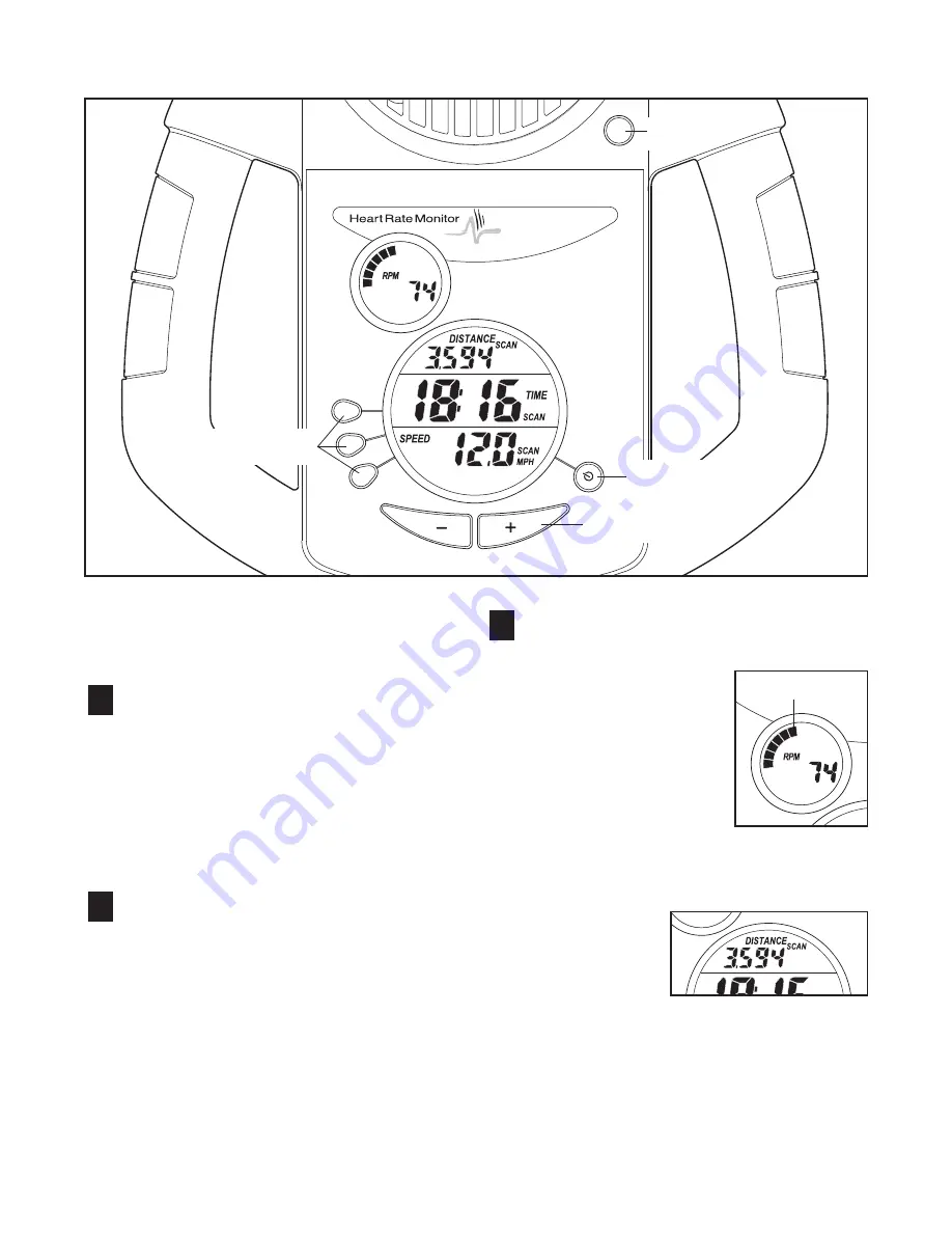
The easy-to-use console offers a selection of features

designed to help you get the most from your workouts.

Follow the instructions below to operate the console.

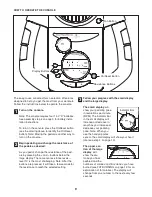
Turn on the console.

Note: The console requires four 1.5V “D” batteries.

See assembly step 4 on page 5 for battery instal-

lation instructions.

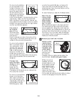
To turn on the console, press the On/Reset button

(see the drawing above to identify the On/Reset

button). Note: Moving the pedals is another way to

turn on the console.

Begin pedaling and change the resistance of

the pedals as desired.

As you pedal, change the resistance of the ped-

als by pressing the + and – buttons below the

large display. There are ten resistance levels—

level 10 is the most challenging. Note: After the

buttons are pressed, it will take a few seconds for

the resistance to reach the selected setting.

Follow your progress with the small display

and the large display.

The small display

will

show your pedaling pace,

in revolutions per minute

(RPM). The indicator bar

in the small display will

increase or decrease in

length as you increase or

decrease your pedaling

pace. Note: When you

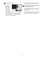
use the handgrip pulse

sensor, the small display will show your heart

rate (see step 4 on page 10).

The upper sec-

tion of the large

display

will

show the dis-

tance you have

pedaled and the

numbers of

calories

and

fat calories

you have

burned (see FAT BURNING on page 13 for an

explanation of fat calories). The display will

change from one number to the next every few

seconds.

2

3

1

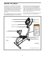
Display Buttons

Fan Button

On/Reset Button

Resistance Buttons

HOW TO OPERATE THE CONSOLE

Indicator Bar

Summary of Contents for 735 Ekg Bike

Page 1: ...PFEVEX29832 Serial No QUESTIONS As a manufacturer we are committed to providing com plete customer satisfaction If you have questions or if there are missing parts please call Or write ICON Health Fitness Ltd Customer Service Department Unit 4 Revie Road Industrial Estate Revie Road Beeston Leeds LS118JG UK email csuk iconeurope com 08457 089 009 Class HC Fitness Product ...

Page 2: ... exercise cycle do not arch your back 9 If you feel pain or dizziness whilst exercising stop immediately and cool down 10 The exercise cycle does not have a freewheel the pedals will continue to move until the fly wheel stops 11 The pulse sensor is not a medical device Various factors including the user s move ment may affect the accuracy of heart rate readings The pulse sensor is intended only as...

Page 3: ... cycle If you have questions after reading this manual please call our Customer Service Department toll free at 08457 089 009 To help us assist you please note the product model number and serial number before calling The model number is PFEVEX29832 The serial number can be found on a decal attached to the exercise cycle see the front cover of this manual Before reading further please familiarise ...

Page 4: ...y the small parts used in assembly The number in parenthesis below each drawing refers to the key number of the part from the PART LIST on page 14 The second number refers to the quantity needed for assembly Note Some small parts may have been pre attached for shipping If a part is not in the parts bag check to see if it has been pre attached M10 x 65mm Carriage Bolt 65 4 M8 Nylon Locknut 10 4 M10...

Page 5: ...ion shown connect the Upper Wire Harness 36 to the Lower Wire Harness 43 Slide the Upright 13 onto the Frame 1 Be careful to avoid pinching the Wire Harnesses 36 43 Attach the Upright to the Frame with three M8 x 25mm Button Screws 14 and three M8 Split Washers 64 Attach the Water Bottle Holder 6 to the Upright 13 with two M4 x 22mm Screws 53 2 63 63 4 The Console 16 requires four D batteries not ...

Page 6: ... turn the Knob clock wise until it is tight 1 5 28 5 Slide the two slots in the Handlebar Clamp 49 onto the two indicated tabs on the Upright 13 Lift the bottom of the Handlebar Clamp away from the Upright and insert the Handlebar 15 between the Handlebar Clamp and the Upright Centre the Handlebar and rotate it to the desired position Slide an M8 Washer 67 onto the Adjustment Handle 9 Insert the A...

Page 7: ...ise into the Right Crank Arm Important Tighten both Pedals as firmly as possible After using the exercise cycle for one week retighten the Pedals For best performance the Pedals must be kept tightened Adjust the Left Pedal Strap 25 to the desired posi tion and press the end of the Pedal Strap onto the tab on the Left Pedal 24 Adjust the Right Pedal Strap not shown in the same way 9 24 42 25 Tab 8 ...

Page 8: ...s into one of the holes in the seat post Then turn the knob clockwise until it is tight HOW TO ADJUST THE HANDLEBAR The handlebar can be adjusted to the position that is the most comfortable for you To adjust the handlebar first turn the adjustment han dle counterclock wise to loosen it Note The adjust ment handle works like a spanner Turn the handle counter clockwise pull it away from the handleb...

Page 9: ...st challenging Note After the buttons are pressed it will take a few seconds for the resistance to reach the selected setting Follow your progress with the small display and the large display The small display will show your pedaling pace in revolutions per minute RPM The indicator bar in the small display will increase or decrease in length as you increase or decrease your pedaling pace Note When...

Page 10: ...sistance level press the lower but ton on the left side of the large display until only the word SPEED or RESIS TANCE appears make sure that the word SCAN does not appear To again view both your pedaling speed and the resistance level press the lower button until the word SCAN reappears To reset the displays press the On Reset button Note The con sole can show speed and dis tance in either miles o...

Page 11: ...fan will turn off to conserve the batteries Rotate the thumb wheel on the right side of the console to pivot the fan to the desired angle When you are finished exercising the console will automatically turn off If the pedals are not moved for a few seconds the displays will pause and the time will flash in the large display If the pedals are not moved and the console but tons are not pressed for a...

Page 12: ... must be removed Remove the seven Screws 52 from the Right Side Shield 18 Next remove the Screw 59 from the right side of the Side Shield Cover 19 Using an adjustable wrench turn the Left Pedal 24 clockwise and remove it Next remove the two Screws 66 from the Left Side Shield 17 Remove the Screw 59 from the left side of the Side Shield Cover 19 and lift it off Gently remove the Left Side Shield Ne...

Page 13: ...xercise Aerobic Exercise If your goal is to strengthen your cardiovascular sys tem your exercise must be aerobic Aerobic exer cise is activity that requires large amounts of oxygen for prolonged periods of time This increases the demand on the heart to pump blood to the muscles and on the lungs to oxygenate the blood For aerobic exercise adjust the intensity of your exercise until your heart rate ...

Page 14: ...agnet 39 2 Small Pulley Washer 40 1 Reed Switch Sensor Wire 41 1 C Magnet 42 1 Left Crank Arm 43 1 Lower Wire Harness 44 2 Crank Bearing 45 1 Resistance Cable 46 1 Resistance Motor 47 1 Return Spring 48 4 M5 Washer 49 1 Handlebar Clamp 50 2 Wheel 51 2 M10 x 45mm Button Bolt 52 7 M4 x 25mm Screw 53 2 M4 x 22mm Screw 54 1 Pulley 55 1 Belt 56 2 Flange Screw 57 1 Right Crank Arm 58 1 9mm Spacer 59 2 M...

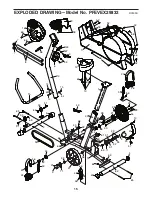
Page 15: ...6 66 52 36 12 28 44 15 26 27 57 56 20 4 23 65 7 8 55 30 68 38 54 21 29 29 35 35 16 66 66 6 49 53 9 65 2 51 50 63 4 4 50 51 63 66 46 48 48 66 40 43 67 5 64 10 64 37 10 41 47 45 3 3 11 11 31 31 31 32 34 39 60 61 69 33 58 14 64 64 14 14 EXPLODED DRAWING Model No PFEVEX29832 R0505A ...

Page 16: ...strial Estate Revie Road Beeston Leeds LS118JG UK Tel Outside the UK 0 444 113 387 7133 Fax 0 444 113 387 7125 To help us assist you please be prepared to give the following information the MODEL NUMBER of the product PFEVEX29832 the NAME of the product PROFORM 735 EKG exercise cycle the SERIAL NUMBER of the product see the front cover of this manual the KEY NUMBER and DESCRIPTION of the part s se...

Reviews: