background image

25


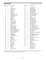
Frame


Front Stabilizer


Rear Stabilizer


Upright


Shield Cover


Handlebar


Console


Right Handlebar Cover


Left Handlebar Cover


10 

Seat Bracket


11 

Seat Carriage


12 

Pulse Bar


13 

Backrest


14 

Backrest Cover


15 

Seat


16 

Right Pedal/Strap


17 

Right Crank Arm


18 

Left Pedal/Strap


19 

Left Crank Arm


20 

Crank


21 

Right Front Shield


22 

Left Front Shield


23 

Right Seat Shield


24 

Left Seat Shield


25 

M4 x 16mm Phillips Screw


26 

Right Front Stabilizer Cap


27 

Left Front Stabilizer Cap


28 

Rear Stabilizer Cap


29 

Magnet


30 

Leveling Foot


31 

Foot/Bumper


32 

Seat Carriage Cap


33 

Brake


34 

Drive Belt


35 

Seat Lever


36 

Seat Handle


37 

Seat Lever Bracket


38 

Axle


39 

Upper Roller


40 

Lower Roller


41 

Pulse Grip


42 

Handlebar Cap


43 

Bearing


44 

Snap Ring


45 

Clamp


46 

Reed Switch/Wire


47 

Idler


48 

Eddy Mechanism


49 

Power Adapter


50 

14 

M6 Split Washer


51 

Resistance Motor


52 

M6 Large Washer


53 

Snap Fastener


54 

M4 x 25mm Screw


55 

M4 x 10mm Flange Screw


56 

16 

M4 x 16mm Screw


57 

M6 x 16mm Screw


58 

Pulley


59 

Crank Arm Cap


60 

10 

M8 x 16mm Screw


61 

16 

M8 Split Washer


62 

M10 x 95mm Screw


63 

M8 x 45mm Screw


64 

5/16" Flange Screw


65 

M6 x 50mm Screw


66 

17 

M6 Washer


67 

1/4" x 14mm Screw


68 

M4 x 13mm Bright Screw


69 

1/4" x 16mm Screw


70 

M4 x 13mm Flange Screw


71 

M6 x 20mm Flat Head Screw


72 

Pulse Bar Pulse Wire


73 

M8 x 20mm Bolt


74 

M8 Locknut


75 

Frame Pulse Wire/Receptacle


76 

Main Wire


77 

M6 x 15mm Shoulder Screw


78 

M6 x 20mm Hex Screw


79 

20 

M4 x 19mm Screw


80 

10 

Fastener


81 

M4 x 12mm Flange Screw


82 

M8 Jam Nut


83 

Brake Spacer


84 

M10 x 50mm Hex Screw


85 

Wire Clamp


86 

Spacer


87 

Motor Bracket


88 

M6 x 20mm Screw


89 

Foam Grip


90 

M4 x 22mm Screw


–– 

User’’s Manual


–– 

Assembly Tool


–– 

Grease Packet

 Key No.  Qty. 

Description

 Key No.  Qty. 

Description

PART LIST

Model No. PFEX53912.0 R0712A

Note: Specifications are subject to change without notice. For information about ordering replacement parts, see 
the back cover of this manual. *These parts are not illustrated.

Summary of Contents for 6.0 Es Bike

Page 1: ...nt Keep this manual for future reference USER S MANUAL QUESTIONS If you have questions or if parts are damaged or missing DO NOT CONTACT THE STORE please contact Customer Care IMPORTANT Please registe...

Page 2: ...te The decal s may not be shown at actual size PROFORM is a registered trademark of ICON IP Inc TABLE OF CONTENTS WARNING DECAL PLACEMENT 2 IMPORTANT PRECAUTIONS 3 BEFORE YOU BEGIN 4 PART IDENTIFICATI...

Page 3: ...red patio or near water 6 Place the exercise bike on a level surface with at least 2 ft 0 6 m of clearance around the exercise bike To protect the floor or carpet from damage place a mat under the exe...

Page 4: ...before you use the exercise bike If you have questions after reading this manual please see the front cover of this manual To help us assist you note the product model number and serial number before...

Page 5: ...0 4 PART IDENTIFICATION CHART Use the drawings below to identify the small parts needed for assembly The number in parentheses below each drawing is the key number of the part from the PART LIST near...

Page 6: ...tabilizer 3 to the Frame 1 with two M10 x 95mm Screws 62 Remove the packing material ASSEMBLY 62 2 1 1 2 3 62 1 Welded Tubes Wheel To hire an authorized service technician to assemble this product cal...

Page 7: ...the wire tie inside the Upright 4 Then locate the Main Wire 76 and the Frame Pulse Wire 75 inside the Frame 1 Tie the lower end of the wire tie to the ends of the Main Wire 76 and the Frame Pulse Wire...

Page 8: ...Avoid pinching the wires Attach the Console 7 to the Upright 4 with four M4 x 16mm Screws 56 6 Insert the Main Wire 76 and the Frame Pulse Wire 75 upward through the indicated hole in the Upright 4 5...

Page 9: ...und the Handlebar 6 and the Upright 4 with four M4 x 22mm Screws 90 9 Attach the Seat 15 to the Seat Carriage 11 with four M6 x 50mm Screws 65 and four M6 Washers 66 only two of each are shown Note Th...

Page 10: ...t the Pulse Bar 12 so that the Pulse Grips 41 face upward Tip Avoid pinching the Pulse Bar Pulse Wire 72 While a second person holds the Pulse Bar 12 attach the Pulse Bar to the Seat Carriage 11 with...

Page 11: ...irmly tighten the Right Pedal 16 clockwise into the Right Crank Arm 17 Firmly tighten the Left Pedal not shown counterclockwise into the Left Crank Arm not shown Adjust the right strap to the desired...

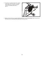
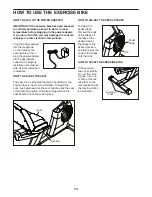
Page 12: ...se bike To plug the Power Adapter into an outlet see HOW TO PLUG IN THE POWER ADAPTER on page 13 15 Make sure that all parts are properly tightened before you use the exercise bike Note Extra parts ma...

Page 13: ...ADJUST THE SEAT The seat can be adjusted forward or backward to the position that is the most comfortable To adjust the seat push downward on the seat handle slide the seat to the desired position an...

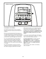
Page 14: ...iFit Live mode that enables the console to communicate with your wire less network through an optional iFit Live module With the iFit Live mode you can download personal ized workouts create your own...

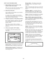
Page 15: ...r kilometers Pulse This display mode will show your heart rate when you use the handgrip heart rate monitor see step 5 Resistance Resist This display mode will show the resistance level of the pedals...

Page 16: ...most accurate heart rate reading hold the contacts for at least 15 seconds If the display does not show your heart rate make sure that your hands are positioned as described Be careful not to move yo...

Page 17: ...t of the profile will begin to flash If a different resis tance level and or target speed is programmed for the next segment the resistance level and or target speed will appear in the display for a f...

Page 18: ...a speed that is comfortable for you You can manually change the resistance of the pedals as desired during the workout by pressing the Quick Resistance buttons Note If you manually change the resistan...

Page 19: ...kout press one of the iFit Live buttons Before some workouts will download you must add them to your schedule on www iFit com Press the Map button the Train button or the Lose Wt button to download th...

Page 20: ...have completed The other lines will show other competitors The end of the matrix represents the end of the race 7 Measure your heart rate if desired See step 5 on page 16 8 When you are finished exer...

Page 21: ...connected to the console If an iFit Live module is connected to the console the display will show the words WIFI MODULE or USB MODULE If no module is connected the display will show the words NO IFIT...

Page 22: ...equipment does cause harmful interference to radio or television reception which can be determined by turning the equipment off and on try to correct the interference by one or more of the following m...

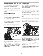
Page 23: ...dapter and turn the Pulley for a moment Repeat these actions until the console displays correct feedback When the reed switch is correctly adjusted reattach the shield cover HOW TO ADJUST THE DRIVE BE...

Page 24: ...c Exercise If your goal is to strengthen your cardiovascular system you must perform aerobic exercise which is activity that requires large amounts of oxygen for prolonged periods of time For aerobic...

Page 25: ...ance Motor 52 1 M6 Large Washer 53 1 Snap Fastener 54 3 M4 x 25mm Screw 55 2 M4 x 10mm Flange Screw 56 16 M4 x 16mm Screw 57 3 M6 x 16mm Screw 58 1 Pulley 59 2 Crank Arm Cap 60 10 M8 x 16mm Screw 61 1...

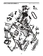
Page 26: ...5 46 47 48 51 58 59 59 60 61 60 61 61 60 61 60 60 61 60 61 61 62 62 63 64 64 61 61 66 66 66 69 69 69 69 67 57 73 73 74 74 61 61 52 77 78 81 84 34 82 56 82 86 56 89 90 90 56 88 56 56 56 79 56 56 76 75...

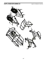
Page 27: ...27 10 13 14 15 22 21 24 23 65 65 66 66 80 80 79 79 79 79 79 79 79 54 79 79 54 79 79 79 54 71 71 79 53 25 EXPLODED DRAWING B Model No PFEX53912 0 R0712A...

Page 28: ...or liable for indirect special or consequential damages arising out of or in con nection with the use or performance of the product damages with respect to any economic loss loss of property loss of r...

Reviews: