background image

3

    WARNING:

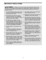
 To reduce the risk of serious injury, read all important precautions and 

instructions in this manual and all warnings on your elliptical before using your elliptical. ICON 

assumes no responsibility for personal injury or property damage sustained by or through the 

use of this product.

1.  It is the responsibility of the owner to ensure 

that all users of the elliptical are adequately 

informed of all precautions.

2.  Before beginning any exercise program, 

consult your physician. This is especially 

important for persons over age 35 or persons 

with pre-existing health problems.

3.  The elliptical is not intended for use by 

persons with reduced physical, sensory, or 

mental capabilities or lack of experience and 

knowledge, unless they are given supervi-

sion or instruction about use of the elliptical 

by someone responsible for their safety.

4.  Use the elliptical only as described in this 

manual. 

5.  The elliptical is intended for home use only. 

Do not use the elliptical in a commercial, 

rental, or institutional setting.

6.  Keep the elliptical indoors, away from mois-

ture and dust. Do not put the elliptical in a 

garage or covered patio, or near water. 

7.  Place the elliptical on a level surface, with at 

least 3 ft. (0.9 m) of clearance in the front and 

rear of the elliptical and 2 ft. (0.6 m) on each 

side. To protect the floor or carpet from dam-

age, place a mat under the elliptical.

8.  Inspect and properly tighten all parts each 

time the elliptical is used. Replace any worn 

parts immediately.

9.  Keep children under age 13 and pets away 

from the elliptical at all times.

10. The elliptical should not be used by persons 

weighing more than 275 lbs. (125 kg).

11. Wear appropriate clothes while exercising; 

do not wear loose clothes that could become 

caught on the elliptical. Always wear athletic 

shoes for foot protection while exercising.

12. Hold the handlebars or the upper body arms 

when mounting, dismounting, or using the 

elliptical.

13. The heart rate monitor is not a medical 

device. Various factors may affect the accu-

racy of heart rate readings. The heart rate 

monitor is intended only as an exercise aid in 

determining heart rate trends in general.

14. The elliptical does not have a freewheel; the 

pedals will continue to move until the fly-

wheel stops. Reduce your pedaling speed in 

a controlled way.

15. Keep your back straight while using the 

elliptical; do not arch your back.

16. Over exercising may result in serious injury 

or death. If you feel faint, if you become short 

of breath, or if you experience pain while 

exercising, stop immediately and cool down.

IMPORTANT PRECAUTIONS

Summary of Contents for 325 CSE

Page 1: ...eep this manual for future reference www iconeurope com CUSTOMER SERVICE UNITED KINGDOM Call 0330 123 1045 From Ireland 053 92 36102 Website www iconsupport eu E mail csuk iconeurope com Write ICON Health Fitness Ltd Unit 4 Westgate Court Silkwood Park OSSETT WF5 9TT UNITED KINGDOM AUSTRALIA Call 1800 993 770 E mail australiacc iconfitness com Write ICON Health Fitness PO Box 635 WINSTON HILLS NSW...

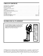
Page 2: ...roid and Google Play are trademarks of Google Inc The BLUETOOTH word mark and logos are registered trademarks of Bluetooth SIG Inc and are used under license IOS is a trademark or registered trademark of Cisco in the U S and other countries and is used under license TABLE OF CONTENTS WARNING DECAL PLACEMENT WARNING DECAL PLACEMENT 2 IMPORTANT PRECAUTIONS 3 BEFORE YOU BEGIN 4 PART IDENTIFICATION CH...

Page 3: ... surface with at least 3 ft 0 9 m of clearance in the front and rear of the elliptical and 2 ft 0 6 m on each side To protect the floor or carpet from dam age place a mat under the elliptical 8 Inspect and properly tighten all parts each time the elliptical is used Replace any worn parts immediately 9 Keep children under age 13 and pets away from the elliptical at all times 10 The elliptical shoul...

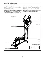
Page 4: ...ead this manual carefully before you use the elliptical If you have questions after reading this manual please see the front cover of this manual To help us assist you note the product model number and serial number before contacting us The model number and the location of the serial number decal are shown on the front cover of this manual Before reading further please familiarize yourself with th...

Page 5: ...w 52 8 M4 x 12mm Screw 89 4 M10 Curved Washer 90 1 M10 x 77mm Bolt 7 1 PART IDENTIFICATION CHART Use the drawings below to identify the small parts needed for assembly The number in parentheses below each drawing is the key number of the part from the PART LIST near the end of this manual The number following the key number is the quantity needed for assembly Note If a part is not in the hardware ...

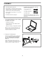
Page 6: ... parts do not use power tools ASSEMBLY 1 2 Identify the Front Stabilizer 63 Orient the Front Stabilizer 63 as indicated by the sticker Make sure that the large holes A in the Front Stabilizer are facing the Frame 1 While a second person lifts the front of the Frame 1 attach the Front Stabilizer 63 to the Frame with two M10 x 68mm Screws 34 63 34 A 1 2 1 Go to www iconsupport eu on your computer an...

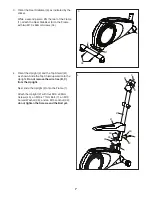
Page 7: ...9 1 3 4 4 Orient the Upright 2 and the Top Shield 41 as shown Slide the Top Shield upward onto the Upright Do not remove the wire ties B C from the Upright Next slide the Upright 2 onto the Frame 1 Attach the Upright 2 with four M10 x 20mm Screws 40 an M10 x 77mm Bolt 7 an M10 Curved Washer 90 and an M10 Locknut 33 do not tighten the Screws and the Bolt yet 2 41 B B C 1 40 40 7 33 90 40 ...

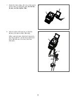
Page 8: ...e Upright 2 with two M4 x 16mm Screws 52 2 29 52 6 Identify the Left and Right Handlebars 85 86 Tip Avoid pinching the Pulse Wires 84 Attach the Left and Right Handlebars 85 86 to the Upright 2 with an M8 x 77mm Bolt 79 and an M8 Jam Nut 38 do not tighten the Bolt yet Make sure that the M8 x 77mm Bolt 79 is inserted through the bottom hole in the Left and Right Handlebars 85 86 and the Upright 2 N...

Page 9: ... start all the Screws and then tighten them 8 Untie and discard the wire ties on the Wire Harness 73 and the Pulse Wires 84 While a second person holds the Console 23 near the Upright 2 connect the console wires to the Wire Harness 73 and to the Pulse Wires 84 8 2 23 73 84 23 89 32 ...

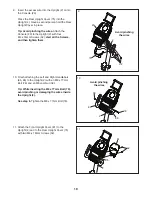
Page 10: ...e Screws and then tighten them 23 Avoid pinching the wires Avoid pinching the wires 75 52 10 Finish attaching the Left and Right Handlebars 85 86 to the Upright 2 with an M8 x 77mm Bolt 79 and an M8 Jam Nut 38 Tip While inserting the M8 x 77mm Bolt 79 avoid pinching or damaging the wires inside the Upright 2 See step 6 Tighten the M8 x 77mm Bolt 79 38 85 86 79 2 2 11 Attach the Front Upright Cover...

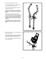
Page 11: ...dy Leg 5 with three M8 x 41mm Bolts 50 and three M8 Jam Nuts 38 start all the Jam Nuts and then tighten them Make sure that the Jam Nuts are inside the hexagonal holes D Assemble the Left Upper Body Arm 6 and the other Upper Body Leg 5 in the same way D Grease 26 69 69 2 13 13 Insert the Pivot Axle 26 into the Upright 2 and center the Pivot Axle Using a small plastic bag to keep your fingers clean...

Page 12: ...t slide the right Upper Body Arm Cover 42 upward Then press the tabs on an Axle Cap 46 into the Upper Body Arm Spacer 47 Repeat this action on the left side of the elliptical Then slide the Upper Body Arm Cover 42 downward to cover the M8 x 41mm Bolts not shown Repeat this action on the left side of the elliptical 15 Identify the Right Pedal 14 and the Right Pedal Arm 12 Attach the Right Pedal 14 ...

Page 13: ...epeat this step on the left side of the elliptical 74 40 83 12 80 Grease 17 17 See assembly steps 4 and 5 Tighten the M10 x 20mm Screws 40 and the M10 x 77mm Bolt 7 Then press the Top Shield 41 into place Next apply a small amount of grease to an M6 Bolt Set 25 Hold the end of the Right Pedal Arm 12 inside the bracket on the right Upper Body Leg 5 Attach the right Upper Body Leg 5 to the Right Ped...

Page 14: ... parts may be included To protect the floor or carpet from damage place a mat under the elliptical 18 Plug the Power Adapter 88 into the receptacle on the frame of the trainer Note To plug the Power Adapter 88 into an outlet see HOW TO PLUG IN THE POWER ADAPTER on page 15 18 52 ...

Page 15: ... the level ing feet beneath the rear stabilizer until the rocking motion is eliminated HOW TO PLUG IN THE POWER ADAPTER IMPORTANT If the elliptical has been exposed to cold temperatures allow it to warm to room tem perature before you plug in the power adapter If you do not do this you may damage the console displays or other electronic components Plug the power adapter into the receptacle on the ...

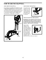
Page 16: ...Note The elliptical does not have a free wheel the pedals will continue to move until the flywheel stops When the pedals are stationary step off the highest pedal first Then step off the lowest pedal HOW TO USE THE TABLET HOLDER IMPORTANT The tablet holder is designed for use with most full size tablets Do not place any other electronic device or object in the tablet holder To insert a tab let int...

Page 17: ...ou can also connect your tablet to the console and use the iFit Bluetooth Tablet app to record and track your workout information The console also offers a selection of onboard work outs Each onboard workout automatically changes the resistance of the pedals and prompts you to maintain a target power output as it guides you through an effec tive workout You can even listen to your favorite workout...

Page 18: ... press a button it will take a moment for the pedals to reach the selected resistance level 5 Do interval training if desired As you exercise you can alternate between intervals of low intensity recovery exercise and intervals of high intensity work exercise if desired To create a recovery interval first adjust the resistance of the pedals to the desired level Then press and hold the Recovery butt...

Page 19: ...your progress with the display The display can show the following workout information Calories CALS The approximate number of calories you have burned Distance MI or KI The distance that you have pedaled in miles or kilometers Pace Your pedaling speed in minutes per mile or minutes per kilometer Pulse heart symbol Your heart rate when you use the handgrip heart rate monitor or a compatible heart r...

Page 20: ...ld the handgrip heart rate monitor with your palms resting against the contacts Avoid moving your hands or gripping the contacts tightly When your pulse is detected your heart rate will be shown in the display For the most accurate heart rate reading hold the contacts for at least 15 seconds If the display does not show your heart rate make sure that your hands are positioned as described Be caref...

Page 21: ...be programmed for consecutive segments At the end of each segment of the workout a series of tones will sound The resistance level for the next segment will appear in the display for a few seconds to alert you The resistance of the pedals will then change The power ring will show a flashing indicator that represents the power output target for the segment The solid bar represents your actual power...

Page 22: ... fat or to strengthen your cardiovascular system the key to achieving the best results is to maintain the proper heart rate during your workouts The optional chest heart rate monitor will enable you to continuously monitor your heart rate while you exercise helping you to reach your personal fitness goals To purchase a chest heart rate moni tor please see the front cover of this manual Note The co...

Page 23: ...the console pairing number will appear in the display When a connection is established the LED on the console will flash red twice Note If there is more than one compatible heart rate monitor near the console the console will connect to the heart rate monitor with the strongest signal To disconnect your heart rate monitor from the console press and hold the iFit Sync button on the console until th...

Page 24: ...ual IMPORTANT To avoid damaging the console use only a manufacturer supplied regulated power adapter HOW TO ADJUST THE REED SWITCH If the console does not display correct feedback the reed switch should be adjusted To adjust the reed switch first unplug the power adapter Using a standard screwdriver remove the Top Shield 41 Note For clarity the right pedal disc is not shown in the drawing below Lo...

Page 25: ...nd Right Pedal Arms 11 12 See EXPLODED DRAWING A on page 30 Using a standard screwdriver remove the left and right Pedal Discs 15 Next identify the Left and Right Shields 3 4 Remove all of the M4 x 16mm Screws 52 from the Left and Right Shields Then remove the two M6 x 18mm Screws 43 Then remove the Left Shield 3 Loosen the M8 x 22mm Screw 65 and turn the M10 x 60mm Bolt 62 until the Drive Belt 19...

Page 26: ...ic Exercise If your goal is to strengthen your cardiovascular system you must perform aerobic exercise which is activity that requires large amounts of oxygen for prolonged periods of time For aerobic exercise adjust the intensity of your exercise until your heart rate is near the highest number in your training zone WORKOUT GUIDELINES Warming Up Start with 5 to 10 minutes of stretch ing and light...

Page 27: ...illes Stretch With one leg in front of the other reach forward and place your hands against a wall Keep your back leg straight and your back foot flat on the floor Bend your front leg lean forward and move your hips toward the wall Hold for 15 counts then relax Repeat 3 times for each leg To cause further stretching of the achilles tendons bend your back leg as well Stretches Calves achilles tendo...

Page 28: ...28 NOTES ...

Page 29: ... Arm Spacer 48 2 Frame Spacer 49 6 Upper Body Arm Bushing 50 6 M8 x 41mm Bolt 51 4 M10 x 22mm Washer 52 28 M4 x 16mm Screw 53 1 Reed Switch Wire 54 1 Clamp 55 3 M8 Washer 56 2 M8 x 25mm Screw 57 1 Mechanism Axle 58 2 Magnet 59 2 Wiring Clamp 60 4 Front Pedal Arm Bushing 61 1 Pulley 62 1 M10 x 60mm Bolt 63 1 Front Stabilizer 64 8 Mushroom Fastener 65 1 M8 x 22mm Screw 66 2 M6 Locknut 67 2 M10 Thin ...

Page 30: ... 69 52 64 64 52 52 52 52 3 41 44 49 50 38 42 2 23 29 52 75 32 87 86 79 38 84 85 84 81 40 40 40 40 82 52 89 42 6 44 24 50 50 38 38 49 5 25 36 48 47 49 49 69 55 56 46 15 15 52 52 43 43 52 87 25 7 33 90 EXPLODED DRAWING A Model No PFEVEL39616 0 R1016A ...

Page 31: ... 20 16 61 52 52 53 71 55 59 78 65 62 57 51 88 67 67 58 58 21 34 63 22 83 39 37 40 27 52 74 77 21 34 80 20 70 31 68 30 60 74 40 83 37 39 76 76 60 18 52 66 27 52 35 10 45 28 51 52 59 66 54 73 EXPLODED DRAWING B Model No PFEVEL39616 0 R1016A ...

Page 32: ...ST and the EXPLODED DRAWING near the end of this manual ORDERING REPLACEMENT PARTS This electronic product must not be disposed of in municipal waste To preserve the environment this product must be recycled after its useful life as required by law Please use recycling facilities that are authorized to collect this type of waste in your area In doing so you will help to conserve natural resources ...

Reviews: