Pro-face PS-3000B Series Hardware Manual Download Page 67

PS-3000B Series Hardware Manual

3-12

3.2.4

CF Card Insertion/Removal

„

When inserting the CF Card
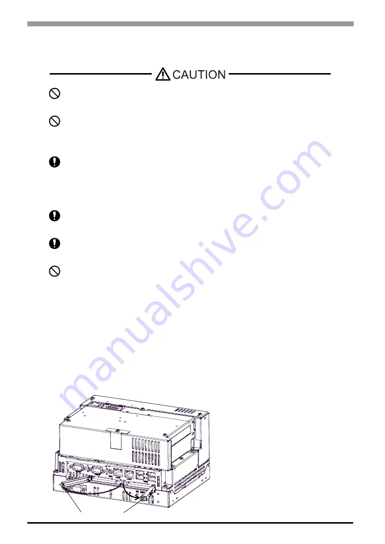
(1)

Remove the CF Card cover.

Prior to inserting or removing a CF Card, be sure to confirm that the PS-B unit is turned 

OFF. If you do not, CF Card internal data may be damaged or lost or the OS may stop.

While a CF Card is being accessed (IDE Access Lamp: Lit in green), NEVER turn OFF or 

reset the PS-B, or insert or remove the CF Card. If you do not, CF Card internal data may 

be damaged or lost.

Prior to inserting a CF Card, familiarize yourself with the CF Card’s front and rear face 

orientation, as well as the CF Card connector’s position. If the CF Card is not correctly 

positioned when it is inserted into the Multi Unit, the CF Card’s internal data, CF Card and 

the PS-B unit may be damaged or broken.

Be sure to use only CF Cards manufactured by the Pro-face. The CF Card’s internal data 

may be damaged when using another manufacturer’s CF Card.

Once PS-B data is lost, it cannot be recovered. Since accidental data loss can occur at any 

time, be sure to back up all PS-B screen and CF Card data regularly.

Be sure to follow the instructions given below to prevent the CF Card’s internal data from 

being destroyed or a CF Card malfunction from occurring:

DO NOT bend the CF Card.

DO NOT drop or strike the CF Card against another object.

Keep the CF Card dry.

DO NOT touch the CF Card connectors.

DO NOT disassemble or modify the CF Card.

CF Card Cover

(This figure is PS3000-BA.)

Summary of Contents for PS-3000B Series

Page 1: ...Hardware Manual PS 3000B Series Industrial automation Elincom Group European Union www elinco eu Russia www elinc ru...

Page 2: ...rks of their respective owners NOTICE 1 Copying this manual s contents either in whole or in part is prohibited without the express permission of Digital Electronics Corporation Japan 2 The informatio...

Page 3: ...t unit operation Be sure to design your system so that a communication fault between the PS B and its host controller will not cause equipment to malfunction This is to prevent any possibility of bodi...

Page 4: ...he manual Doing so may cause a fire or an electric shock Do not connect or disconnect Host and PS B unit communication cables while the PS B is turned ON The PS B uses a lithium battery for backing up...

Page 5: ...remove the CF Card while the PS B unit s CF Card or hard disk is being accessed Otherwise CF Card and the hard disk internal data may be damaged or lost When the product is disposed of it should be do...

Page 6: ...t use paint thinner or organic solvents to remove dirt or oil from the PS B unit s surface Instead use a soft cloth moistened with a diluted neutral detergent After turning OFF the PS B be sure to wai...

Page 7: ...ning or a product limitation Be sure to follow the instructions given with this icon to ensure the safe operation of the PS B Indicates useful or important supplemental information Contains additional...

Page 8: ...ssing please contact your local PS B distributor immediately PS B Unit 1 Installation Guides Set of Japanese Set of English Warning Caution Information 1 Installation Fasteners Set 1 Fasteners 2 Screw...

Page 9: ...rature must be checked on the final product in which the PS B is installed CE Marking PS3000 BA units are CE marked products that conform to EMC directives and Low Voltage Directives EN55011 Class A E...

Page 10: ...ection against harmful interference when the equipment is operated in a commercial environment This equipment generates uses and can radiate radio frequency energy and if not installed and used in acc...

Page 11: ...10...

Page 12: ...BA 1 5 1 3 2 PS3001 BD 1 7 1 4 Prior to Operating the PS B Unit 1 9 1 4 1 Power Supply 1 9 Chapter 2 Specifications 2 1 PS3000 BA 2 2 2 1 1 General Specifications 2 2 2 1 2 Performance Specifications...

Page 13: ...oval 3 12 3 2 5 USB Cable Clamp Attachment Removal 3 14 3 3 Wiring Precautions 3 16 3 3 1 Connecting the Power Cord 3 16 3 3 2 Connecting the Power Supply 3 20 3 3 3 Grounding 3 21 3 3 4 I O Signal Li...

Page 14: ...stem Design 2 Accessories 3 Part Names and Functions 4 Prior to Operating the PS B Unit This chapter describes peripheral devices that can be connected to PS B Series units along with the name and fun...

Page 15: ...mary CF Card I F TYPE ll 1 port Secondary CF Card I F TYPE ll 1 port Speaker Out I F Hub Speaker Central Network Line HDD Unit 1 2 Main Memory Module 1 2 CF Cards 2 2 Main Memory I F Peripherals comme...

Page 16: ...ry CF Card I F TYPE ll 1 port Secondary CF Card I F TYPE ll 1 port Speaker Out I F Hub Speaker Central Network Line HDD Unit 1 2 Main Memory Module 1 2 CF Cards 2 Main Memory I F Peripherals commercia...

Page 17: ...MB CA3 CFCALL 256MB 0 Type 1 256MB CA3 CFCALL 512MB 0 Type 1 512MB CA6 CFCALL 1GB 01 Type 1 1GB USB Front Cable CA5 USBEXT 01 1m Extension cable attaching USB port to the pane Analog RGB cable FP CV02...

Page 18: ...with System Set SW Please refer to Switches page 2 10 for details E Expansion Board Cover F Expansion Board Support G Expansion Unit Interface 1 port Used to attach the PCI Unit H Serial Interface COM...

Page 19: ...d Type I II compliant is available IDE type connection 1 P Analog RGB Interface A mini D sub 15 pin socket is used to connect a RGB monitor on the market or FP Series unit manufactured by Pro face Q P...

Page 20: ...PS B s circuit board D USB Holder Attachment Area E Power Connector F Serial Interface COM1 RS 232C D sub 9 pin plug type G Serial Interface COM2 RS 232C RS 422 RS 485 Changeover RI 5V Changeover D su...

Page 21: ...cover and insert the CF Card CF Card Type I II compliant is available IDE type connection 1 O Power LED RAS Status Lamp ON P HDD IDE Access Lamp DISK Power supply voltage 5 VDC 5 Output current Each p...

Page 22: ...ate that Windows has been shut down and the power is provided only for the electric circuit to boot system This Soft OFF State is different from what is System Standby set by Windows Power State No Po...

Page 23: ...PS 3000B Series Hardware Manual 1 10...

Page 24: ...2 1 2 Specifications 1 PS3000 BA 2 PS3001 BD This chapter describes the general functional and interface specifications of the PS B as well as its part names and dimensions...

Page 25: ...90 RH Not condensing wet bulb temperature 39 C or less Wet bulb temperature with HDD 29 C or less Storage Humidity 10 to 90 RH Not condensing wet bulb temperature 39 C or less Dust Free of dust Pollut...

Page 26: ...years whichever comes first at an operating temperature of 20 C and 333 hours of operation per month HDD access frequency of 20 or less Using the Hard Disk in an environment that is excessively hot a...

Page 27: ...SG terminals Functional grounding D type Same for FG and SG terminals Structure Rating Equivalent to IP20 Feature size All in one Installation configuration In cabin installation Cooling Method Force...

Page 28: ...Master CF Card I F USB USB 2 0 compatible front 4 ports Connector USB type A Power Supply Voltage DC5V 5 Output Current Each port 500mA max 4 ports total 500mA max Maximum communication distance 5m L...

Page 29: ...PCI board and temperature derating Slot Type PCI 2 2 5V Board Size 106 68 x 174 63mm 4 20 x 6 88in Power Supply Capacity DC5V DC12V DC 12V DC3 3V Power Consumption 1 0A 0 25A 0 1A 0 5A 100 10 85W 70 7...

Page 30: ...aging the RS 232C RS 422 RS 485 circuit be sure to connect the 5 SG Signal Ground terminal Interfit Bracket 4 40 UNC Pin Arrangement Pin No RS 232C Signal Name Direction Meaning 1 CD Input Carrier Det...

Page 31: ...nal Ready 5 GND Signal Ground 6 DR DSR Input Data Set Ready 7 RS RTS Output Request to Send 8 CS CTS Input Clear to Send 9 CI RI 5V 1 1 To change the RI 5V setting of 9 pin set System Set switch to th...

Page 32: ...D of COM1 COM2 RS 232C to the host unit s Signal Ground terminal Be sure to confirm what settings will be used by the other device and set the slide switches accordingly Failure to do so can result in...

Page 33: ...built in HDD unit 1 Unscrew the screws 2 from the Expansion Board Cover and remove the cover When replacing the cover the torque required for these screws is 0 5 to 0 6N m 2 Unscrew the screws 2 of t...

Page 34: ...N m 3 Unscrew the screws 4 of the HDD unit remove the cable connector from IDE I F while lifting up the HDD unit and remove it To replace the HDD unit connect the cable connector to IDE I F securely a...

Page 35: ...er Options Advanced Power buttons is operated when pressing the Reset SW For Windows XP the mode of When I press the power button on my computer that is selected from Control panel Performance and Mai...

Page 36: ...5 Used for the system Reserved Reserved Factory Settings OFF 6 Changes Reset SW mode Power button Reset SW Factory Settings OFF 7 Used for the system Reserved Reserved Factory Settings OFF 8 Changes...

Page 37: ...2 2 If you use the termination resistance base your settings on the connection specifications 6 Switches the RX termination resistance ON OFF Inserts termination resistance of 220 between RXA and RXB...

Page 38: ...Chapter 2 Specifications 2 15 Serial Mode Select Switches SW4 to SW10 operate as shown in the circuit diagram below TXD RTS SW4 SW9 SW10 SW5 SW7 SW6 SW8 TXA TXB RXA RXB RTS Automatic control COM2...

Page 39: ...PS3000 BA Installation Fasteners Attached Dimensions Unit mm in Front Right Side 130 0 3 5 12 0 01 2 R2 5 0 10 217 8 54 17 0 67 Left Side Top 130 0 3 5 12 0 01 124 4 88 255 10 04 238 0 4 9 37 0 02 130...

Page 40: ...in case of cable bending The dimensions given here are representative values depending on the type of connection cable used Therefore they are all intended for reference only Right 48 5 1 91 42 2 1 66...

Page 41: ...installation panel Use M4 size screws Unit mm in Horizontal mounting Wall mounting 1 Wall mounting 2 Vertical panel Horizontal panel Horizontal mounting Wall mounting 1 130 0 3 5 12 0 01 217 8 54 238...

Page 42: ...b temperature 39 C or less Dust Free of dust Pollution Degree For use in Pollution Degree 2 environment Corrosive gas Free of corrosive gases Atmosphere Using height 800 to 1114hPa 300 to 2 000 meters...

Page 43: ...d SG terminals Functional grounding D type Same for FG and SG terminals Structure Rating Equivalent to IP20 Feature size All in one Installation configuration In cabin installation Cooling Method Natu...

Page 44: ...t 4 ports Connector USB type A Power Supply Voltage DC5V 5 Output Current Each port 500mA max 4 ports total 500mA max Maximum communication distance 5m LAN Front 2 ports This interface uses an RJ 45 t...

Page 45: ...damaging the RS 232C RS 422 RS 485 circuit be sure to connect the 5 SG Signal Ground terminal Interfit Bracket 4 40 UNC Pin Arrangement Pin No RS 232C Signal Name Direction Meaning 1 CD Input Carrier...

Page 46: ...Ready 5 GND Signal Ground 6 DR DSR Input Data Set Ready 7 RS RTS Output Request to Send 8 CS CTS Input Clear to Send 9 CI RI 5V 1 1 To change the RI 5V setting of 9 pin set System Set switch to the d...

Page 47: ...5 GND of COM1 COM2 RS 232C to the host unit s Signal Ground terminal Be sure to confirm what settings will be used by the other device and set the slide switches accordingly Failure to do so can resul...

Page 48: ...signified The switches are on the PS B s circuit board To change the switch settings The switches are on the PS B s circuit board First of all remove the cover Unscrew the screws 2 of the Maintenance...

Page 49: ...er Options Advanced Power buttons is operated when pressing the Reset SW For Windows XP the mode of When I press the power button on my computer that is selected from Control panel Performance and Mai...

Page 50: ...for the system Reserved Reserved Factory Settings OFF 6 Changes Reset SW mode Power button Reset SW Factory Settings OFF 7 Used for the system Reserved Reserved Factory Settings OFF 8 Changes COM2 RI...

Page 51: ...2 2 If you use the termination resistance base your settings on the connection specifications 6 Switches the RX termination resistance ON OFF Inserts termination resistance of 220 between RXA and RXB...

Page 52: ...Chapter 2 Specifications 2 29 Serial Mode Select Switches SW4 to SW10 operate as shown in the circuit diagram below TXD RTS SW4 SW9 SW10 SW5 SW7 SW6 SW8 TXA TXB RXA RXB RTS Automatic control COM2...

Page 53: ...PS3001 BD Installation Fasteners Attached Dimensions Unit mm in Front Right Side 130 0 3 5 12 0 01 2 R2 5 0 10 217 8 54 17 0 67 Left Side Top 69 2 72 255 10 04 238 0 4 9 37 0 02 130 0 3 5 12 0 01 164...

Page 54: ...ase of cable bending The dimensions given here are representative values depending on the type of connection cable used Therefore they are all intended for reference only Right Front Top 2 8 0 11 16 3...

Page 55: ...installation panel Use M4 size screws Unit mm in Horizontal mounting Wall mounting 1 Wall mounting 2 Vertical panel Horizontal panel Horizontal mounting Wall mounting 1 130 0 3 5 12 0 01 217 8 54 238...

Page 56: ...3 1 3 Installation and Wiring 1 Installation Uninstallation 2 Peripheral Devices Installation 3 Wiring Precautions...

Page 57: ...n be mounted horizontally on a panel as well as attached to a wall To prevent abnormally high temperatures from occurring inside the PS B unit mount the unit on a horizontal panel or attach it to a ve...

Page 58: ...ace minimum is neces sary at the front for cable curve Wall mounting 1 Front Wall mounting 2 Right side 50 1 97 Horizontal mounting Front Wall mounting 2 Front 50 1 97 50 1 97 50 1 97 50 1 97 120 4 72...

Page 59: ...e that heat from surrounding equipment does not cause the PS B to exceed its standard operating temperature Creating Screw Holes Create the correct sized openings required to install the PS B using th...

Page 60: ...ration panel s door etc can move i e open or close due consideration should be given to the PS B unit s weight Determine the thickness of the panel in consideration of its material and strength as wel...

Page 61: ...le CF Cards or Expansion boards PCI boards Failure to do so can result in an electric shock If the PS B unit is in the Soft OFF Status power is supplied to a part of circuits even when no screen conne...

Page 62: ...orque should be 0 5 to 0 6N m 6 For PS3000 BA replace the Expansion Board Cover and reattach two 2 attachment screws lastly The torque should be 0 5 to 0 6N m 3 2 2 Expansion Board PCI Installation A...

Page 63: ...l 3 8 2 Unscrew a screw of the expansion board support and remove the expansion board support 3 Unscrew the screws 2 from the Expansion Board Cover and remove the cover Only for PS3000 BA This figure...

Page 64: ...into the expansion board connector and secure it in place using the filler panel s screw The necessary torque is 0 5N m to 0 6N m 6 Place back both of the expansion board cover and expansion board sup...

Page 65: ...HDD unit Since the HDD unit is a precision instrument that has a low resistance to shocks be sure it is neither hit by nor pressed strongly against another object when installing it Even when the PS B...

Page 66: ...these screws is 0 5 to 0 6N m 3 Unscrew the screws 4 of the HDD unit remove the cable connector from IDE I F while lifting up the HDD unit and remove it To replace the HDD unit connect the cable conne...

Page 67: ...If the CF Card is not correctly positioned when it is inserted into the Multi Unit the CF Card s internal data CF Card and the PS B unit may be damaged or broken Be sure to use only CF Cards manufactu...

Page 68: ...from the CF Card slot 4 After inserting removing the CF Card be sure to replace the CF Card cover and secure it in place using the attachment screw Backup of CF Card The CF Card has a data overwrite l...

Page 69: ...B connectors 2 For PS3000 BA unscrew the screws 2 from the Expansion Board Cover and open the cover When using two or more USB ports be sure to first connect one USB cable to the upper USB connector a...

Page 70: ...Cover and reattach two 2 attachment screws The torque required for these screws is 0 5 to 0 6N m Removing the USB Cable Clamp 1 To remove the clamp from the USB cables push down on the clamp strap s c...

Page 71: ...er switch on the DC type PS B unit be sure to attach a breaker type switch to its power cord When the FG terminal is connected be sure the wire is grounded When the FG terminal is connected be sure th...

Page 72: ...to 12 AWG Conductor Type Simple or Stranded Wire 1 1 If the Conductor s end individual wires are not twisted correctly the end wires may either short against each other or against an electrode Conduc...

Page 73: ...nnected correctly The torque required to tighten these screws is 0 5 to 0 6N m To prevent the possibility of a terminal short use a pin terminal that has an insulating sleeve Power Cord Diameter 0 75...

Page 74: ...each hole Release the Opening button to clamp the pin in place 5 After inserting all three pins insert the Power Plug into the Power Connector at PS B Fix the plug with two 2 slot screws Recommended D...

Page 75: ...ut signal lines Connect a lightening surge absorber as shown in the diagram to deal with power surges To avoid excess noise make the power cord as short as possible 24V DC input unit is must be used w...

Page 76: ...terminals are internally connected in the PS B When connecting an external device to the PS B using the SG terminal be sure to check that no short circuit loop is created when you setup the system Th...

Page 77: ...Manual 3 22 3 3 4 I O Signal Line Placement Input and output signal lines must be separated from the power control cables for operating circuits If this is not possible use a shielded cable and groun...

Page 78: ...1 4 Maintenance 1 Cleaning the Fan Filter 2 Periodic Check Points 3 Replacing the Internal Battery This chapter explains cautions and inspection criteria that will ensure trouble free use of the PS B...

Page 79: ...as shown below and remove the fan unit Remove the filter between the fan cover and the fan 3 Clean the filter completely If stubborn dirt or stains are present wash the filter with a neutral detergent...

Page 80: ...HDD 29 C or less PS3001 BD 10 to 90 RH Not condensing wet bulb temperature 39 C or less Is the operating atmosphere free of corrosive gasses When using the PS B unit inside an enclosure the enclosure...

Page 81: ...nitialized Configure the BIOS settings again after replacing the battery There is a danger of explosion if the PS B unit s battery is incorrectly replaced This battery should be replaced with equivale...

Page 82: ...Interface Specifications Switches page 2 25 1 Be sure to confirm that power is not supplied to the PS B unit and open the unit 2 Insert a tool having a flat tip such as insulated slot head screwdriver...

Page 83: ...r first with the plus pole facing upward Push the battery from above until you hear the click to fit it in the battery holder 4 Return the PS B unit to the original condition Be sure the battery s plu...

Reviews: