22
E
ngl
is
h
Installation
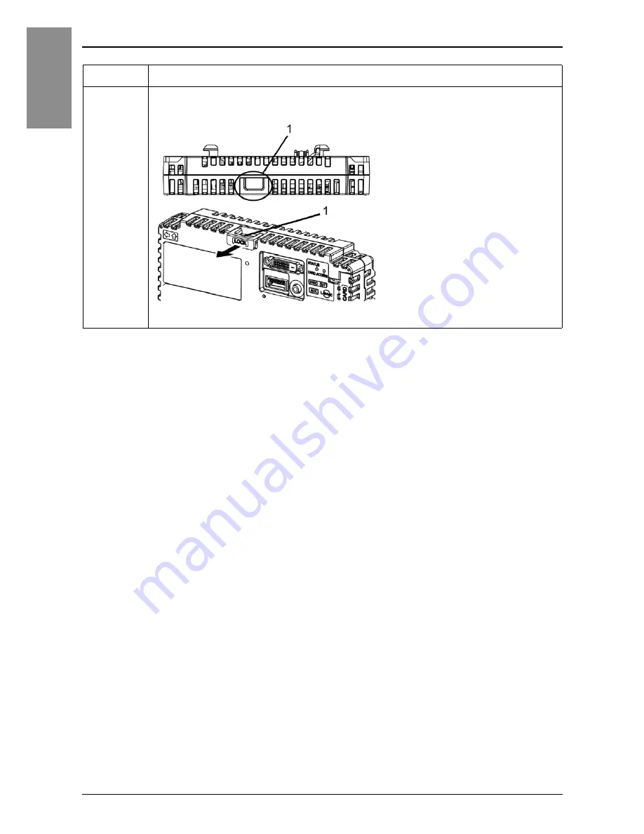
Step
Action
1
Pull the LOCK forward on the top of the Box Module to release the lock as illustrated.
1 LOCK
Page 1: ...SP5000 Series Box Module Installation Guide HRB78714_07_EN...
Page 2: ...l Specifications 13 Environmental Specifications 13 Interface Interface Caution 14 Serial Interface 14 Auxiliary Output Speaker Output Interface AUX 18 DVI D Output Interface Only for Open Box 19 Inst...
Page 3: ...4 English Maintenance Cleaning This Product 31 Replacing the Battery 31 Standards Standards 33...
Page 4: ...k at the equipment to become familiar with the device before trying to install operate or maintain it The following special messages may appear throughout this documentation or on the equipment to war...
Page 5: ...er referred to as Schneider Electric for any consequences arising out of the use of this material A qualified person is one who has skills and knowledge related to the construction and operation of el...
Page 6: ...y Module refer to the SP5000 Series Display Module Installation Guide Additionally you can also connect the DC Power Supply Adapter for Box Module by Pro face model number PFXZCDADEXP1 1 SP 5B40 suppo...
Page 7: ...SB Clamp Type A 1 port 2 sets for Power Box 3 sets for Open Box 1 clip and 1 tie 3 SP5000 Series Box Module Installation Guide this guide 1 4 Warning Caution Information 1 5 End user License Agreement...
Page 8: ...is assigned to every Pro face product as a universal model number For more information on product models and their matching global codes please refer to the following URL http www pro face com trans...
Page 9: ...mini B Interface E Expansion Unit Interface Cover EXT F Storage Card Cover G System Card Cover H USB Type A Interface I Ethernet Interface Ethernet1 1 J Ethernet Interface Ethernet2 1 K Serial Interf...
Page 10: ...LED See page 12 F USB Type A Interface G USB mini B Interface H Expansion Unit Interface Cover EXT I Storage Card Cover J System Card Cover K USB Type A Interface L Ethernet Interface Ethernet1 1 M E...
Page 11: ...operation RUN Flashing 1 In operation STOP In operation STOP Orange Flashing Software starting up Red ON Power is ON Flashing 1 In operation Major error In operation Major error Red Green Alternating...
Page 12: ...m Display Module or DC Power Supply Adapter for Box Module 1 Power Consumption Primary Power Supply Max 25 W 35 W 25 W When power is not supplied to external devices 12 5 W or less 22 5 W or less 15 W...
Page 13: ...within the rated current DANGER ELECTRIC SHOCK AND FIRE When using the SG terminal to connect an external device to this product Verify that a short circuit loop is not created when you set up the sys...
Page 14: ...of each serial interface is explained on the respective reference page The communication method can be switched via the software The initial setting is RS 422 RS 485 COM1 COM2 SP 5B10 5B40 5B41 RS 23...
Page 15: ...put totals 0 25 A Interfit bracket is 4 40 UNC Recommendations Cable Connector XM3D 0921 manufactured by OMRON Corporation Cable Cover XM2S 0913 manufactured by OMRON Corporation Jack Screw 4 40 UNC X...
Page 16: ...Cover XM2S 0913 manufactured by OMRON Corporation Jack Screw 4 40 UNC XM2Z 0073 manufactured by OMRON Corporation Pin Number RS 422 RS 485 Signal Name Direction Meaning 1 RDA Input Receive Data A 2 R...
Page 17: ...B Pin Number 6 ALARM BUZZER C Pin Number 7 ALARM BUZZER D Load E External Power Cable connection side Pin Number Signal Name Direction Meaning 1 LineOut Output Line Out 2 LineOut_GND Output Line Out G...
Page 18: ...IELD 4 NC 5 NC 6 DDC Clock Output 7 DDC Data Input Output 8 NC 9 TMDS DATA 1 Output 10 TMDS DATA 1 Output 11 TMDS DATA 1 SHIELD 12 NC 13 NC 14 5 Vdc Power 15 GND Ground 16 SP 5B40 NC SP 5B41 Hot Plug...
Page 19: ...x 768 When the screen output mode is set to clone mode the maximum display resolution of the display module is the same as the display resolution of DVI D output which is XGA 1 024 x 768 DVI D output...
Page 20: ...dware or cables Unplug the power cable from the Display Module or DC Power Supply Adapter for Box Module and the power supply Always use a properly rated voltage sensing device to confirm power is off...
Page 21: ...22 English Installation Step Action 1 Pull the LOCK forward on the top of the Box Module to release the lock as illustrated 1 LOCK...
Page 22: ...and right of the Box Module into the two holes on the back of the Display Module or DC Power Supply Adapter for Box Module to attach the Box Module 2 Protruding points 3 Box Module 4 Holes for inserti...
Page 23: ...the Display Module to the panel Refer to the DC Power Supply Adapter for Box Module Installation Guide on how to mount the DC Power Supply Adapter for Box Module to the panel 3 Fully push on the LOCK...
Page 24: ...death or serious injury NOTICE EQUIPMENT DAMAGE When this product is mounted vertically from the panel first remove the Display Module or DC Power Supply Adapter for Box Module then remove the Box Mod...
Page 25: ...ection indicated by arrow A in the diagram and remove it by sliding in the direction indicated by arrow B CAUTION RISK OF INJURY Do not drop the Box Module when you remove it from the Display Module o...
Page 26: ...nsure that power communication and accessory connections do not place excessive stress on the ports Consider the vibration in the environment when making this determination Securely attach power commu...
Page 27: ...overlaps The clip matches the 27 to 43 5 mm 1 06 to 1 71 in length of the USB connector NOTE When installing clamps to reduce cable stress onto both USB1 and USB2 at USB1 overlay the clip on the side...
Page 28: ...through the center of the tie loop and that the tie can pass through the head You can substitute the tie provided with PFXZCBCLUSA1 by Pro face or other commercially available ties with a width of 4 8...
Page 29: ...Remove the AUX connector from this product prior to wiring Strip wires only to the required length Do not solder the wire itself Failure to follow these instructions will result in death or serious i...
Page 30: ...to replace the battery Use only the replacement battery for this product model number PFXZCBBT1 1 Safety alert symbol see the safety messages as follows 2 Battery NOTICE EQUIPMENT DAMAGE Power off th...
Page 31: ...o use 12 to 24 Vdc Always check whether your device is DC powered before applying power Failure to follow these instructions will result in death or serious injury DANGER EXPLOSION FIRE OR CHEMICAL HA...
Page 32: ...o install operate modify maintain service or otherwise alter this product except as permitted in this manual Unpermitted actions may impair the suitability of this product for Class I Division 2 opera...
Page 33: ...placement est d sign non dangereux Le non respect de ces instructions provoquera la mort ou des blessures graves Inquiry Do you have any questions about difficulties with your unit Please access our s...