background image


2.2.


Power supply 

SP5000 has a DC power supply type only. When replacing GP-3750T AC type with 
SP5000 series, changing to DC power supply is required. For the detailed electric 
specifications, see the hardware manual. 


2.3.


USB Transfer cable 

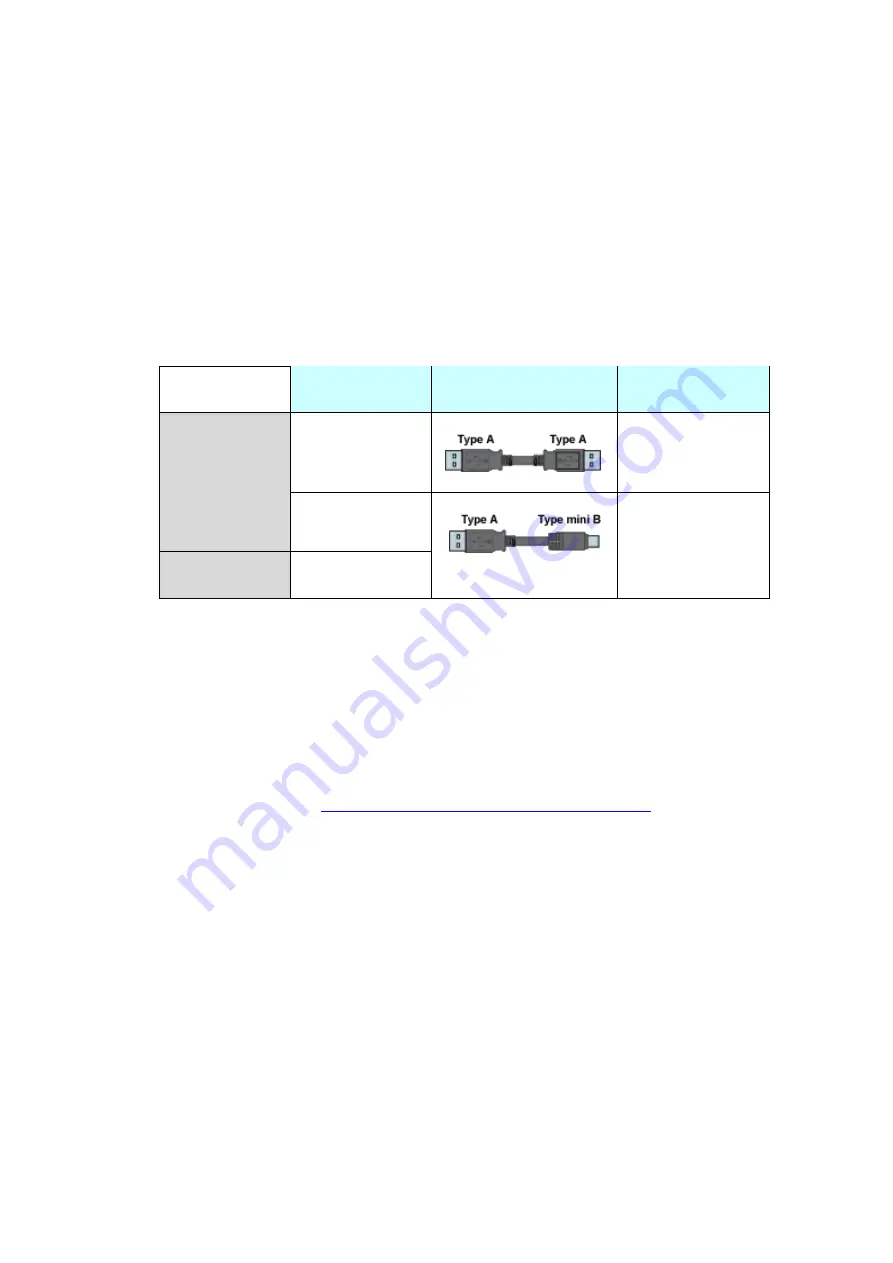
Like the GP3000 series, a USB transfer cable (CA3-USBCB-01) can be used for the 
SP5000 series. Also, a USB (Type mini B) cable (ZC9USCBMB1) and commercial 
cables can be used on the SP5000 series’ side.


Model 

Connector Type 

Connector on 

Display 

Options 

CA3-USBCB-01 


USB (Type A) 

ZC9USCBMB1 


USB (Type mini B) 

Commercial 

Item 


2.4.


Interface 


2.4.1.


Serial Interface 

The SP5000 series has a COM port on the side of box module. 
The pin array and the shapes of the plug and the socket differ between GP-3750T 
COM2 port and SP-5B00(Standard box) COM port. The PLC connection cable that 
used to be connected to GP3000 Series via its COM2 port cannot be used as it is. 
For details, refer to 

Chapter 4 Communication with Device/PLC

. Cables other 

than that can be used as they are. 
When both the COM1 port and the COM2 port have the RS-422/485 setting, only 
the  COM2  port  can  be  used  for  RS-422/485  connection  after  replacement  to 
SP-5B00(Standard box). 


2.4.2.


Auxiliary I/O Interface (AUX) 

There is no Auxiliary I/O interface (AUX) on SP-5B00(Standard box). 
If using AUX, please select SP-5B10(Power box) for the box module. 


Summary of Contents for AGP3750-T1-AF

Page 1: ...Easy Smooth Replacement Guidebook GP 3750T SP 5700TP Premium Display SP 5B00 Standard Box The 4th Edition Nov 2018...

Page 2: ...ware that you could not replace to SP5000 series see 2 7 Display and Box of SP5000 series can be separated so you can freely select a suitable combination of them according to use This guidebook intro...

Page 3: ...4 5 CF CARD INTERFACE 10 2 5 PERIPHERAL UNITS AND OPTION UNITS 11 2 5 1 BARCODE 2D TWO DIMENSIONAL CODE READER CONNECTION 11 2 5 2 PRINTER CONNECTION 11 2 5 3 EXPANSION UNIT 11 2 5 4 ISOLATION UNIT 12...

Page 4: ...26 4 1 SHAPES AND COMMUNICATION METHOD OF COM PORTS 26 4 2 SIGNALS OF COM PORTS 26 4 3 CABLE DIAGRAM AT THE TIME OF REPLACEMENT 27 4 4 MULTILINK CONNECTION 27 CHAPTER 5 APPENDIX 28 5 1 CHANGING THE S...

Page 5: ...W383 5 H282 5mm External Dimensions W395 H294 D60mm NEW W397 H296 D67mm 2 Touch Panel Type Resistive film Analog UP Resistive film Analog multi touch Memory Application 16MB UP 64MB SRAM SRAM 320KB UP...

Page 6: ...2 4 2 Video Input I F see 2 7 Sound Input I F 3 see 2 4 3 Sound Output I F Speaker output 70mW 3 see 2 4 4 Expansion Unit I F Communication Unit 3 see 2 5 3 Expansion Unit I F Image Unit see 2 7 Expa...

Page 7: ...Chapter 2 Compatibility of Hardware 2 1 Locations of connector Connector locations of GP 3750T and SP 5700TP SP 5B00 GP 3750T SP 5700TP Premium display SP 5B00 Standard box...

Page 8: ...I F COM2 4 Ethernet I F 5 USB I F Type A 6 USB I F Type mini B 7 Storage Card Cover There s a SD card I F for storage under the cover 8 CF card I F 9 Expansion Unit I F Communication Unit 10 Auxiliar...

Page 9: ...2 4 1 Serial Interface The SP5000 series has a COM port on the side of box module The pin array and the shapes of the plug and the socket differ between GP 3750T COM2 port and SP 5B00 Standard box CO...

Page 10: ...F Card Interface SP5000 series is not equipped with a CF card slot But a SD card slot and a USB interfaces are installed In order to use the GP 3750T data saved in the CF card and the functions using...

Page 11: ...per operation of the printer before use 2 5 3 Expansion Unit The expansion unit cannot be used with SP 5B00 Standard box If you used PROFIBUS unit for GP3000 series model CA5 PFSALL EX 01 please repla...

Page 12: ...5B00 is not needed a backup battery for Clock Supercapacitor electric double layer capacitor can be back up clock data Please note the following points When the voltage from the Supercapacitor is low...

Page 13: ...For more detail please refer to the following http www proface co jp otasuke qa server_ex replace 2 10 Other Notes Do not expose SP5000 series to direct sunlight Do not use SP5000 series outdoors Do...

Page 14: ...ion Change the received data on GP Pro EX Check and modify the data on GP Pro EX Transfer the screen data to SP5000 series Check the connection between SP5000 series and a PLC in the GP Pro EX Device...

Page 15: ...of cables are available A USB transfer cable model CA3 USBCB 01 A USB data transfer cable model ZC9USCBMB1 A commercial USB cable USB Type A mini B Possible to send receive a screen via a SD card a U...

Page 16: ...4 Change the Display Unit Type 1 Connect your PC and GP3000 Series with a USB transfer cable If the driver of the cable has not been installed on your PC yet a dialog box will appear Please follow th...

Page 17: ...GP Pro EX 3 Make sure that the Device in the Transfer Settings Information is set to USB If not click the Transfer Setting button to open the Transfer Setting dialog box Select USB in the Communicatio...

Page 18: ...n 5 Click Receive Project and the following dialog box will appear Specify a place to save the received data in and a project file name and then click Save to start transfer NOTE When a file exists th...

Page 19: ...llowing dialog box will appear during transfer Specify a place to save the CF card data in Click OK and the Receive Project dialog box will return and transfer will be completed 2 SP5000 series that i...

Page 20: ...Tool 3 4 Change the Display Unit Type Open the received project file prx of GP3000 Series on GP Pro EX and change the display unit type to SP5000 series 1 Open the received project file prx on GP Pro...

Page 21: ...ries You can transfer data to SP5000 series via An USB transfer cable model CA3 USBCB 01 An USB data transfer cable model ZC9USCBMB1 A commercial USB cable USB Type A mini B A SD card USB storage devi...

Page 22: ...en installed on you PC a dialog box will appear Please follow the instructions NOTE The Hardware Installation dialog box as shown below may appear during installing the USB driver depending on the sec...

Page 23: ...r on the display unit After transferring a project file once this screen will not appear again 3 On the GP Pro EX s State Toolbar click the Transfer Project icon to open the Transfer Tool To transfer...

Page 24: ...Settings field and click OK 5 Click Send Project to start transfer When the following dialog box appears click Yes This dialog box doesn t appear when the same project file is sent again 6 The followi...

Page 25: ...file will be displayed 8 Close the Transfer Tool 9 Click the X mark on top right of the screen or Project Exit to close GP Pro EX 3 6 Differences of software Some functions supported by GP3000 Series...

Page 26: ...the COM2 port on GP 3750T and the COM2 port on SP 5B00 Standard box Pin Arrangement Pin No GP 3750T SP 5B00 Standard box Signal Name Direction Meaning Signal Name Direction Meaning 1 TRMRX Terminatio...

Page 27: ...ble For the following case only it can be used for the COM2 on SP 5B00 Standard box if the COM Port Conversion Adapter CA3 ADPCOM 01 is added to the GP s side When an online adapter CA4 ADPONL 01 is a...

Page 28: ...for the external media setting 1 To use a USB flash drive instead of a SD card Solution 1 2 To check or change the SD card s data output destination folder setting Solution 2 Solution 1 Change the SD...

Page 29: ...h the one of USB Storage NOTE To check each function setting of GP Pro EX refer to GP Pro EX Reference Manual 2 Check and change the destination folder setting following the steps below i Click Projec...

Reviews: