23
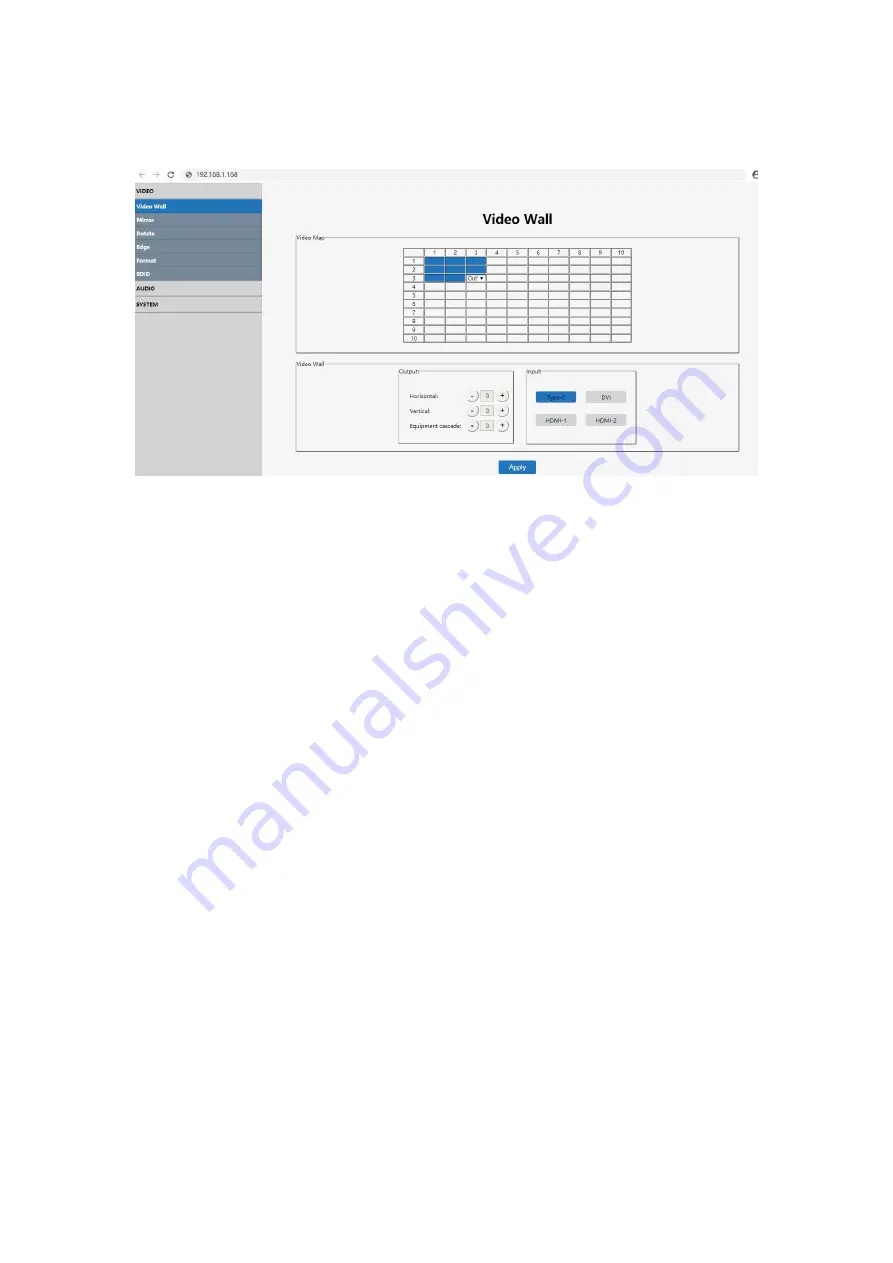
7.5.2 Video wall setting
Note:This interface is used to set up video walls or cascade.
Interface introduction:
(1) Video Map column: to identify the location of the output port mapping, you can
change the output port position through the drop-down menu.
(2) Output column: screens in horizontal and vertical directions, plus the parameters
of the equipment cascade layers.
(3) Input column: source selection for the video wall.(Type-C, DVI, HDMI1,
HDMI2).
(4) Default 2x2 video wall, the device can also realize 1x1 1x4 4x1 2x3 3x2 3x3 and
max 10x10 video walls through cascade.
(5) The max screen amount in the horizontal direction is 10pcs.
(6) The max screen amount in the vertical direction is 10pcs.
(7) The max cascade layer amount is 25 layers.
(8) Note: The parameters can be set up by clicking the "
+
" or "-" key in the Output
column, and mouse clicking to select the input. The selected one has blue color.
Operating instructions
Eg1
:
Select TYPE-C port as input source to make a 2x2 video wall by 1pcs device,
TV 1 ~ 4 are connected to output port 2/4/1/3 for mapping function.
(1) In the Output section, select both the "Horizon" and "Vertical" as number 2, and
the "Equipment Cascade " as number 1(There is only one device. The cascade
layer must be 1, otherwise the setting is invalid).
(2) Then select "Type-C" in the Input section and click "apply".
(3) In the Video Map column, click and select the output ports to out2, out4, out1,
out3 according to TV 1 ~ 4, and then click "apply" to complete the mapping
operation.
Summary of Contents for VWC22V2
Page 3: ...3 WARRANTY 32...
Page 32: ...32...


