Privacy Electronics DS-DVR04 Series User Manual Download Page 27

User Manual of


DS-DVR04, DS-DVR08, DS-

DVR16 Series DVR


1


2


3


4


5


6


7


8


9


10 11


12


13


14


15 16


17


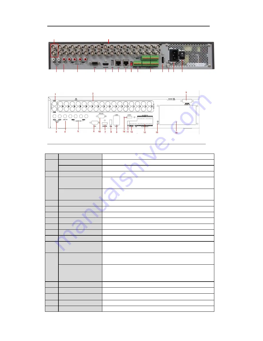
Figure 1.17 Rear Panel of 7332-FH, 7332-WH and 7332HI-SH


Note: 

7324-FH, 7324-WH and 7324HI-SH models provide 24 video input interfaces.


Figure 1.18 Rear Panel of 7332A-WH


Table 1 Description of Rear Panel


No.


Item


Description


1


MAIN VIDEO OUT


BNC connector for video output.


SPOT VIDEO OUT


BNC connector for spot video output.


2


VIDEO IN


BNC connector for analog video input.


RCA connector for audio output. This connector is synchronized with


CVBS AUDIO OUT


CVBS video output.


3


VGA AUDIO OUT


RCA connector for audio output. This connector is synchronized with


VGA video output.


4


LINE IN


RCA connector for two-way audio input.


5


AUDIO IN


RCA connector for audio input.


6


VGA


DB15 connector for VGA output. Display local video output and menu.


7


HDMI


HDMI video output.


8


USB Interface


Connects USB mouse or USB flash memory devices.


9


LAN Interface


RJ45 10M/100M/1000M Ethernet interface.


10


RS-232


Connector for RS-232 devices.


11


Termination Switch


RS-485 termination switch. Up position is not terminated.


Down is terminated with 120Ω resistance.


RS-485 Interface


Connector for RS-485 devices. Connect the T+ and T- terminals to the


R+ and R- terminals of PTZ receiver respectively.


12


K

B


Connect the D+ and D- terminals to Ta and Tb terminals of the controller.


For cascading devices, the first DVR‟s D+ and D- terminals should be


connected with the D+ and D- terminals of the next DVR.


13


Alarm In/Out


Connector for alarm input/output.


14


eSATA


Connects external SATA HDD, DVD-R/W.


15


GND


Ground(needs to be connected when DVR starts up)


16


110~240VAC


110~240VAC power supply.


17


POWER


Switch for turning on/off the device.


25


Summary of Contents for DS-DVR04 Series

Page 1: ...Digital Video Recorder User Manual V2 2 3...

Page 2: ...t accept any interference received including interference that may cause undesired operation EU Conformity Statement This product and if applicable the supplied accessories too are marked with CE and...

Page 3: ...aler This manual is applicable to the following models DS DVR04 DS DVR08 DS DVR16 This manual may contain several technically incorrect places or printing errors and the content is subject to change w...

Page 4: ...nit is properly secured to a rack or shelf Major shocks or jolts to the unit as a result of dropping it may cause damage to the sensitive electronics within the unit Use the device in conjunction with...

Page 5: ...ay sequence of screens is adjustable Live view screen can be switched in group and manual switch and automatic cycle view is also provided the interval of automatic cycle can be adjusted Quick setting...

Page 6: ...signal video input output standard mismatch illegal login network disconnected IP confliction abnormal record HDD error and HDD full etc Alarm event triggers full screen monitoring audio alarm notifyi...

Page 7: ...ansparent channel transmission Note RS 232 serial port is provided for 7300 and 8100 models only Alarm event and exception information can be sent to the remote host Remotely start stop recording Upgr...

Page 8: ...g an Auxiliary Monitor 36 3 2 4 Main Aux Output Switching 37 3 2 5 Quick Setting Toolbar in Live View Mode 37 3 3 Adjusting Live View Settings 40 3 4 Channel zero Encoding 42 3 5 User Logout 43 C H A...

Page 9: ...yback of Multi channel 89 C H A P T E R 7 91 Backup 91 7 1 Backing up Record Files 92 7 1 1 Quick Export 92 7 1 2 Backing up by Normal Video Search 94 7 1 3 Backing up by Event Search 97 7 1 4 Backing...

Page 10: ...g Quota Mode 146 10 5 Checking HDD Status 148 10 6 Checking S M A R T Information 149 10 7 Detecting Bad Sector 150 10 8 Configuring HDD Error Alarms 151 C H A P T E R 11 152 Camera Settings 152 11 1...

Page 11: ...8 13 3 Configuring DST Settings 170 13 4 Configuring More Settings 171 13 5 Managing User Accounts 172 13 5 1 Adding a User 172 13 5 2 Deleting a User 174 13 5 3 Editing a User 175 13 5 4 Changing Pas...

Page 12: ...User Manual of DS DVR04 DS DVR08 DS DVR16 Series DVR C H A P T E R 1 Introduction 11...

Page 13: ...r turns green when NVR is powered up READY The indicator light is green when the device is running normally STATUS 1 The light is green when the IR remote control is enabled 2 The light is red when th...

Page 14: ...and back to the previous menu Keys Enter numeral 5 Enter letters JKL 5 JKL EDIT Delete characters before cursor Check the checkbox and select the ON OFF switch 3 Start stop record clipping in playback...

Page 15: ...s forwards or backwards In the image setting interface the up and down button can adjust the level bar of the image parameters 5 Control Buttons In live view mode these buttons can be used to switch c...

Page 16: ...same time and the SHIFT button is not used Indicator turns orange a when the DVR is controlled by IR remote control with the address from 1 254 and keyboard at the same time and the SHIFT button is us...

Page 17: ...ds and items in menus In Playback mode the Up and Down button is used to speed up and slow down recorded video DIRECTION In All day Playback mode the Left Right button can be used to select the record...

Page 18: ...e is armed GUARD Indicator does not light when the device is disarmed The arm disarm state can be initiated by pressing and holding on the ESC button for more than 3 seconds in live view mode Channel...

Page 19: ...ed to navigate between different fields and items in menus In Playback mode the Up and Down button is used to speed up and slow down recorded video DIRECTION In All day Playback mode the Left Right bu...

Page 20: ...or PTZ Control mode Inputting numbers and characters in Edit mode Switching between different channels in All day Playback mode 4 EDIT Button Editing text fields When editing text fields it will also...

Page 21: ...Control mode it will turn on off PTZ light 17 PTZ Control Buttons Adjusting the iris focus and zoom of a PTZ camera 18 F2 Button Cycle through tab pages Troubleshooting Remote Control Note Make sure y...

Page 22: ...and show the quick set menu Menu Select and enter Double Click Live view Switch single screen and multi screen Left Click Click and Drag PTZ control pan tilt and zoom Tamper proof privacy mask and mot...

Page 23: ...R16 FH WH HH HV series DVR are shown in below Figure 1 6 Rear Panel of 7204FH HH HV Figure 1 7 Rear Panel of 7204 WH 1 2 6 11 3 4 5 7 8 9 10 12 Figure 1 8 Rear Panel of 7216 HH and 7216 HV Note The re...

Page 24: ...22...

Page 25: ...Audio input interfaces Table 1 7 Description of Rear Panel No Item Description 1 VIDEO IN BNC connector for analog video input 2 VIDEO OUT BNC connector for video output 3 USB Interface Connects USB...

Page 26: ...POT VIDEO OUT BNC connector for spot video output 3 HDMI HDMI video output 4 USB Interface Connects USB mouse or USB flash memory devices 5 RS 232 Connector for RS 232 devices 6 VGA DB15 connector for...

Page 27: ...dio input 6 VGA DB15 connector for VGA output Display local video output and menu 7 HDMI HDMI video output 8 USB Interface Connects USB mouse or USB flash memory devices 9 LAN Interface RJ45 10M 100M...

Page 28: ...DB26 connector for audio input 7 VGA DB15 connector for VGA output Display local video output and menu 8 RS 232 Connector for RS 232 devices 9 HDMI HDMI video output 10 USB Interface Connects USB mou...

Page 29: ...ded that an Uninterruptible Power Supply UPS be used in conjunction with the device 2 Press the POWER button on the rear panel The Power indicator LED should turn green indicating that the unit begins...

Page 30: ...User Manual of DS DVR04 DS DVR08 DS DVR16 Series DVR C H A P T E R 2 Getting Started 28...

Page 31: ...d at that moment click You can also choose to use the Start Wizard next time by leaving the Start wizard when device starts checkbox checked 2 Click on the Wizard window to enter the Login window as s...

Page 32: ...ime Settings 6 After the time settings click which takes you to the Network Start Wizard window as shown in Figure 2 4 Note LTN7604 HT only supports 10M 100Mbps NIC type Figure 2 4 Network Configurati...

Page 33: ...the HDD 9 Click to enter the IP Camera Management window as shown in Figure 2 6 Figure 2 6 IP Camera Management 10 Click to search IP Camera Click to add IP Camera 11 After finishing IP Camera settin...

Page 34: ...User Manual of DS DVR04 DS DVR08 DS DVR16 Series DVR Figure 2 8 Copy Record Settings 13 Click to complete the start wizard settings 32...

Page 35: ...User Manual of DS DVR04 DS DVR08 DS DVR16 Series DVR C H A P T E R 3 Live View 33...

Page 36: ...you re on brings you to the Live View mode Live View Icons In the live view mode there are icons at the right top of the screen for each channel showing the status of the record and alarm in the chan...

Page 37: ...e view recording and PTZ controls When both HDMI and VGA are not connected it is used as the main video output for live view playback recording PTZ control and menu operations When the aux output is e...

Page 38: ...mode and the operation for the main output is disabled Note If you enter Aux monitor mode and the Aux monitor is not connected the mouse operation is disabled you need to switch back to the Main outpu...

Page 39: ...uble click on the screen again to switch to the Aux output or click Cancel to cancel the operation 3 Select the Menu Output Mode to Main CVBS from the right click menu on the CVBS output monitor Figur...

Page 40: ...ected area to the full screen You can left click and draw to select the area for zooming in as shown in Figure 3 3 Figure 3 5 Digital Zoom Image Settings Image Settings icon can be selected to enter t...

Page 41: ...ustable value range is 0 255 for the brightness contrast saturation and hue 0 15 for the sharpness level and 0 5 for the denoising level 4 Copy image parameters 1 If you want to copy the image paramet...

Page 42: ...set to 1920 1080 up to 36 division window display is supported By default the system resolution is set to 1280 1024 Note Up to 16 division window display is supported for the CVBS output Dwell Time T...

Page 43: ...nterface 2 Select an output interface and select a screen layout 3 Click to select a screen in the right region and double click to select a channel in the left region Thus the selected channel will b...

Page 44: ...the image quality channel zero encoding is supported as an option for you Steps 1 Enter the Live View Settings interface Menu Configuration Live View 2 Select the Channel Zero Encoding tab Figure 3 10...

Page 45: ...w mode and if you want to do some operation you need to enter user name and password to log in again Steps 1 Enter the Shutdown menu Menu Shutdown Figure 3 11 Shutdown 2 Click Logout Note After you ha...

Page 46: ...User Manual of DS DVR04 DS DVR08 DS DVR16 Series DVR C H A P T E R 4 PTZ Controls 44...

Page 47: ...of the PTZ camera Note All the parameters should be exactly the same as the PTZ camera parameters Only PTZ Protocol can be set for network cameras Example If the PTZ camera has a Baud rate as 115200...

Page 48: ...e the preset Repeat the steps2 4 to save more presets If the number of the presets you want to save is more than 17 you can click and choose the available numbers Figure 4 3 More Presets 4 2 2 Calling...

Page 49: ...g menu in live view mode Figure 4 5 PTZ Toolbar 2 Choose Camera in the list on the menu 3 Choose preset in the Preset list 4 2 3 Customizing Patrols Purpose Patrols can be set to move the PTZ to diffe...

Page 50: ...ey point and speed of patrol The key point is corresponding to the preset The Key Point No determines the order at which the PTZ will follow while cycling through the patrol The Duration refers to the...

Page 51: ...g interface Steps 1 In the PTZ setting interface Menu Camera PTZ More Settings 2 Select the patrol number and then click to call the patrol 3 Click to stop it Figure 4 9 Calling Patrol Calling preset...

Page 52: ...ing to the predefined path Steps 1 Enter the PTZ Control interface Menu Camera PTZ More Settings 2 Choose pattern number in the option box Figure 4 11 PTZ Pattern 3 Click and use your mouse to drag th...

Page 53: ...ure 4 12 PTZ Calling Pattern Call pattern in live view mode Steps 1 In the live view mode press PTZ control on the IR remote control or click PTZ Control icon on the quick setting toolbar 2 And then c...

Page 54: ...iption Icon Description Icon Description Direction button and the Zoom Focus Zoom Focus auto cycle button Iris Iris The speed of the PTZ Light on off Wiper on off movement 3D Zoom Image Preset Central...

Page 55: ...User Manual of DS DVR04 DS DVR08 DS DVR16 Series DVR C H A P T E R 5 Record Settings 53...

Page 56: ...al 2 Check the storage mode of the HDD 1 Click Advanced to check the storage mode of the HDD 2 If the HDD mode is Quota please set the maximum record capacity and maximum picture capacity For detailed...

Page 57: ...9 59 55 Post record The time you set to record after the event or the scheduled time For example when an alarm triggered the recording ends at 11 00 if you set the post record time as 5 seconds it re...

Page 58: ...55...

Page 59: ...step of main stream settings 3 Click Apply to save the settings Note You can click the Restore button to restore the current sub stream settings to the default parameters 4 If you want to copy the cu...

Page 60: ...ble for different models DS DVR04 DS DVR08 DS DVR16 FH WH HH and DS DVR04 DS DVR08 DS DVR16 HV Normal and Motion 7300 and 8100 Normal Motion Alarm Motion Alarm and Motion Alarm Note To enable Motion t...

Page 61: ...57...

Page 62: ...Task 2 Draw the Schedule Steps 1 Click the icon on the right to select a record type Different recording types are available for different models DS DVR04 DS DVR08 DS DVR16 FH WH HH and DS DVR04 DS D...

Page 63: ...58...

Page 64: ...e steps to set schedule for other channels If the settings can also be used to other channels click Copy to enter the Copy Camera interface and then choose the channel to which you want to copy Figure...

Page 65: ...oring audio warning notify the surveillance center and so on In this chapter you can follow the steps to schedule a record which triggered by the detected motion Steps 1 Enter the Motion Detection int...

Page 66: ...which you want the motion detection event to trigger recording 6 Click Apply to save the settings 7 Click OK to back to the upper level menu 8 Exit the Motion Detection menu 3 Enter Schedule settings...

Page 67: ...End time Note Up to 8 periods can be configured for each day And the time periods can t be overlapped each other Repeat the above steps3 6 to schedule motion detection triggered recording for all the...

Page 68: ...alarm triggered recording or capture Steps 1 Enter the Alarm setting interface Menu Configuration Alarm Figure 5 20 Alarm Settings 2 Click Alarm Input tab Figure 5 21 Alarm Settings Alarm Input 1 Sele...

Page 69: ...s Repeat the above steps to configure other alarm input parameters If the setting can also be applied to other alarm inputs click Copy and choose the alarm input number Figure 5 23 Copy Alarm Input 3...

Page 70: ...ng for all cameras by clicking the status bar before Analog to change it to 3 Set recording mode to manual By default the camera is enabled with recording by schedule Click the status bar to change it...

Page 71: ...the Record setting interface Menu Record 2 Choose Holiday on the left bar Figure 5 27 Holiday Settings 3 Enable Edit Holiday schedule 1 Click to enter the Edit interface Figure 5 28 Edit Holiday Setti...

Page 72: ...or Normal from the Type dropdown list 6 If you need all day recording check the All Day checkbox Otherwise leave it blank 7 Set start end time for holiday schedule Note Up to 8 periods can be configu...

Page 73: ...up before you set the HDD property to Redundant For detailed information please refer to Chapter 10 4 Managing HDD Group There should be at least another HDD NetHDD which is in R W mode Steps 1 Enter...

Page 74: ...ries DVR Figure 5 32 Encoding Record 2 Select Camera you want to configure 3 Check the checkbox of the Redundant Record 4 Click Apply to save settings and back to the upper level menu Repeat the above...

Page 75: ...rface 4 Configuring HDD group 1 Choose a group number for the HDD group 2 Click Apply and then in the pop up message box click Yes to save your settings 3 Click OK to back to the upper level menu Repe...

Page 76: ...re 5 35 Playback 2 Select the channels by checking the checkbox to 3 Configure the record type file type and start end time 4 Click Search to show the results Figure 5 36 Playback Search Result 5 Prot...

Page 77: ...ou want to protect Figure 5 39 HDD General Editing 3 Set the HDD to Read only 4 Click OK to save settings and back to the upper level menu Note You can t save any files in a Read only HDD If you want...

Page 78: ...User Manual of DS DVR04 DS DVR08 DS DVR16 Series DVR C H A P T E R 6 Playback 73...

Page 79: ...ant Playback Interface Playback by channel Steps 1 Enter the Playback interface Mouse Right click a channel in live view mode and select from the menu as shown in Figure 6 2 Figure 6 2 Right click Men...

Page 80: ...on Operation Button Operation Button Operation Audio on Mute Start Stop Add Add customized clipping default tag tag Pause reverse Digital Smart play Tag management Reverse play Zoom Search Single fram...

Page 81: ...of channel s in the channel list and then double click to select a date on the calendar Figure 6 5 Playback Calendar Note If there are record files for that camera in that day in the calendar the ico...

Page 82: ...me Interface Button Operation Button Operation Button Operation Button Operation Audio on Start Stop Add Add Mute clipping default tag customized tag Pause reverse Tag Digital Smart play Reverse play...

Page 83: ...ent type e g alarm input and motion detection Steps 1 Enter the playback interface Menu Playback 2 Click and select to enter the Event Playback interface 3 Select Alarm Input as the event type and edi...

Page 84: ...9 59 55 Post play The time you set to play back after the event For example when an alarm triggered the recording ends at 11 00 if you set the post play time as 5 seconds the video plays back till 11...

Page 85: ...n Start Stop Add Add Mute clipping default tag customized tag Pause reverse Tag Digital Smart play Reverse play management Zoom Search Single frame reverse play Pause play Play Stop 30s 30s reverse Si...

Page 86: ...files and position time point Before playing back by tag 1 Enter Playback Menu Playback interface 2 Search and play back the record file s Refer to Chapter 6 1 2 for the detailed information about se...

Page 87: ...t the Start and End time and click to enter Search Result interface Note You can enter keyword in the textbox to search the tag on your command Figure 6 15 Video Search by Tag 4 Click button to play b...

Page 88: ...Start Stop Add Add Mute clipping default tag customized tag Pause reverse Tag Digital Smart play Reverse play management Zoom Search Single frame reverse play Pause play Play Stop 30s 30s reverse Sin...

Page 89: ...Steps 1 Enter Log Information interface Menu Maintenance Log Information Log Search Figure 6 18 Log Search Interface 2 Set search time and type and click 3 Choose a log with record file and click but...

Page 90: ...rd files stored in the external storage devices e g USB flash drives USB HDDs Before you start Please insert the external device s with record files into the device Steps 1 Enter the Playback interfac...

Page 91: ...It is also feasible to use button in toolbar Using the Front Panel For 7300WH FH DVR you can use the front panel buttons to perform the playback Rotate and hold the outer ring on Jog Shuttle counterc...

Page 92: ...area s click button to execute smart search in this area Note Multi area and full screen searching modes are supported Figure 6 2 Draw Area of Smart Search Different video type bars are marked in diff...

Page 93: ...Tag Slow down management Pause reverse Pause play Reverse play play Play Single frame Stop Speed up Single frame reverse play play Previous smart search Next smart search Video search Exit result res...

Page 94: ...mouse to draw a red rectangle and the image within it will be enlarged up to 16 times 7 You can right click to exit the Digital Zoom mode Figure 6 22 Draw Area for Digital Zoom 6 2 4 Reverse Playback...

Page 95: ...User Manual of DS DVR04 DS DVR08 DS DVR16 Series DVR Figure 6 23 4 ch Synchronous Playback Interface 3 Click to play back the record files reversely 90...

Page 96: ...User Manual of DS DVR04 DS DVR08 DS DVR16 Series DVR C H A P T E R 7 Backup 91...

Page 97: ...oose the channel s you want to back up and click Note The time duration of record files on a specified channel cannot exceed one day Otherwise the message box Max 24 hours are allowed for quick export...

Page 98: ...g interface until all record files are exported Figure 7 3 Export Finished 3 Check backup result Choose the record file in Export interface and click button to check it Note The Player player exe will...

Page 99: ...Notes 1 Six different Record types are selectable Continuous Motion Alarm Motion Alarm Motion Alarm Command Triggered and Manual The command triggered record is configured by the platform when the de...

Page 100: ...Export Click and start backup Note If the inserted device is not recognized Click Reconnect device Check for compatibility from vendor You can also format USB flash drives or USB HDDs via the device U...

Page 101: ...ay in the Exporting interface until all record files are exported with pop up message box Export finished Figure 7 9 Export Finished 5 Check backup result Choose the record file in Export interface an...

Page 102: ...Purpose Back up event related record files using USB devices USB flash drives USB HDDs USB writer or DVD R W Quick Backup and Normal Backup are supported Steps 1 Enter Export interface Menu Export Ev...

Page 103: ...els triggered by the selected alarm input You can view detailed information of the record file e g start time end time and file size Note The size of the currently selected files is displayed in the l...

Page 104: ...tay in the Exporting interface until all record files are exported with pop up message Export finished Figure 7 15 Export Finished 4 Check backup result Note The Player player exe will be exported aut...

Page 105: ...layback toolbar to start or stop clipping record file s 3 Quit Playback interface after finishing clipping and you will then be prompted to save the clips Note A maximum of 30 clips can be selected fo...

Page 106: ...y in the Exporting interface until all record files are exported with pop up message Export finished Figure 7 20 Export Finished 6 Check backup result Note The Player player exe will be exported autom...

Page 107: ...earch 2 Select record files you want to back up Click Export button to enter Export interface Note At least one record file shall be selected Figure 7 2 Result of Normal Video Search for Backup 3 Back...

Page 108: ...nter Search Result interface of record files Menu Export Normal Set search condition and click Search button to enter Search Result interface Note At least one channel shall be selected Figure 7 4 Nor...

Page 109: ...ent Click Erase button if you want to erase the files from a re writable CD DVD Note There must be a re writable CD DVD when you make this operation Note If the inserted USB writer or SATA writer is n...

Page 110: ...User Manual of DS DVR04 DS DVR08 DS DVR16 Series DVR C H A P T E R 8 Alarm Settings 105...

Page 111: ...ivity 1 Check the checkbox of Enable Motion Detection to enable motion detection use the mouse to draw detection area s and drag the sensitivity bar to set sensitivity 2 Click the icon of Handling to...

Page 112: ...g schedule to other days Note Time periods shall not be repeated or overlapped Figure 8 4 Set Arming Schedule of Motion Detection 5 Click Handling tab to set up alarm response actions of motion alarm...

Page 113: ...You can set handling method of an external sensor alarm Steps 1 Enter Alarm Settings interface and select an alarm input Menu Configuration Alarm Figure 8 7 Alarm Status Interface 2 Select Alarm Input...

Page 114: ...u can also use Copy to copy an arming schedule to other days Click Apply to save the settings Note Time periods shall not be repeated or overlapped 5 Select Handling tab to set alarm response actions...

Page 115: ...ure 8 10 Set PTZ Linking of Alarm Input 7 If you want to set handling method of another alarm input repeat the above steps or just copy the above settings to it by clicking Copy in Alarm Input Setting...

Page 116: ...oss Figure 8 12 Video Loss Setup Interface 2 Select a channel you want to detect 3 Check the checkbox of Enable Video Loss Alarm 4 Click the icon of Handling to enter the Handling interface 5 Set the...

Page 117: ...the checkbox of Enable Tamper proof Note By default the tamper proof detection is configured in full screen 4 Move the sensitivity bar and choose a proper sensitivity level 5 Click the icon of Handli...

Page 118: ...Disconnected network cable IP Conflicted Duplicated IP address Illegal Login Incorrect user ID or password Input Output Video Standard Mismatch I O video standards do not match Record Exception No sp...

Page 119: ...u must select the channel s you want to make full screen monitoring Menu Camera Motion Handling Trigger Channel Audible Warning Trigger an audible beep when an alarm is detected Notify Surveillance Ce...

Page 120: ...hin each day Note Time periods shall not be repeated or overlapped Figure 8 18 Set Arming Schedule of Alarm Output 3 Repeat the above steps to set up arming schedule of other days of a week You can al...

Page 121: ...dwell time of an alarm output the alarm can be cleared only by clicking Clear button in the following interface Steps Select the alarm output you want to trigger or clear and make related operations...

Page 122: ...User Manual of DS DVR04 DS DVR08 DS DVR16 Series DVR C H A P T E R 9 Network Settings 117...

Page 123: ...WH HH and DS DVR04 DS DVR08 DS DVR16 HV models provide one 10M 100Mbps self adaptive network interface and the 7300WH FH models provide one 10M 100M 1000Mbps self adaptive network interface 3 In the G...

Page 124: ...118...

Page 125: ...s can be configured independently You can select LAN1 or LAN2 in Select NIC field for parameter settings You can select one NIC card as default route And when the system is connecting with the extrane...

Page 126: ...e Mode The two NIC cards use the same IP address and you can select the Main NIC to LAN1 or LAN2 By this way in case of one NIC card failure the device will automatically enable the other standby NIC...

Page 127: ...ce 5 Click the Apply button to save and exit the interface 6 After successful settings the system asks you to reboot the device to enable the new settings and the PPPoE dial up is automatically connec...

Page 128: ...Server Address should be the IP address of the PC that runs IPServer Figure 9 10 IPServer Settings Interface DynDNS 1 Enter Server Address for DynDNS e g members dyndns org 2 In the Device Domain Nam...

Page 129: ...1 Enter the Server Address of the HiDDNS server www hiddns com 2 Enter the Device Domain Name You can register the alias of the device domain name in the HiDDNS server first and then enter the alias...

Page 130: ...vice Domain Name for LTS 1 Enter the Server Address of the LTS server which is ns1 dvrlist com by default 2 Enter the Device Domain Name You can use the alias you registered in the LTS server or defin...

Page 131: ...NTP Port Port of NTP server 5 Click the Apply button to save and exit the interface Note The time synchronization interval can be set from 1 to 10080min and the default value is 60min If the device i...

Page 132: ...establish functional network services for data sharing communications etc If you want to use the UPnP function to enable the fast connection of the device to the WAN via a router you should configure...

Page 133: ...ndicates the port No for port mapping in the router Figure 9 22 External Port Settings Dialog Box 6 You can click Refresh to get the latest status of the port mapping Figure 9 23 UPnP Settings Finishe...

Page 134: ...e interface 9 2 7 Configuring Multicast Purpose The multicast can be configured to realize live view for more than the maximum number of cameras through network A multicast address spans the Class D I...

Page 135: ...128...

Page 136: ...e and exit the menu 9 2 9 Configuring Server and HTTP Ports Purpose You can change the server and HTTP ports in the Network Settings menu The default server port is 8000 and the default HTTP port is 8...

Page 137: ...ranet or the Internet depending on the location of the e mail accounts to which you want to send notification Steps 1 Enter the Network Settings interface Menu Configuration Network 2 Set the IPv4 Add...

Page 138: ...The Email address of sender Select Receivers Select the receiver Up to 3 receivers can be configured Receiver The name of user to be notified Receiver s Address The Email address of user to be notifie...

Page 139: ...tain real time information of device such as linking status MTU sending receiving rate etc Steps 1 Enter the Network Traffic interface Menu Maintenance Net Detect Figure 9 33 Network Traffic Interface...

Page 140: ...in the text field of Destination Address 4 Click the Test button to start testing network delay and packet loss The testing result pops up on the window If the testing is failed the error message box...

Page 141: ...he backup device please check whether it is compatible with the device You can format the backup device if the format is incorrect Figure 9 36 Export Network Packet 4 Click the Export button to start...

Page 142: ...ick Status on the right bottom of the page Figure 9 38 Checking Network Status If the network is normal the following message box pops out Figure 9 39 Network Status Checking Result If the message box...

Page 143: ...of the device Steps 1 Enter the Network Statistics interface Menu Maintenance Net Detect 2 Click the Network Stat tab to enter the Network Statistics menu Figure 9 41 Network Stat Interface 3 View th...

Page 144: ...User Manual of DS DVR04 DS DVR08 DS DVR16 Series DVR C H A P T E R 1 0 HDD Management 137...

Page 145: ...d with your device Steps 1 Enter the HDD Information interface Menu HDD General Figure 10 1 HDD Information Interface 2 Select the HDD to be initialized 3 Click the Init button Figure 10 2 Confirm Ini...

Page 146: ...User Manual of DS DVR04 DS DVR08 DS DVR16 Series DVR Figure 10 3 HDD Status Changes to Normal Note Initializing the HDD will erase all data on it 139...

Page 147: ...HDD Information Interface 2 Click the Add button to enter the Add NetHDD interface as shown in Figure 10 5 Figure 10 5 Adding NetHDD Interface 3 Add the allocated NetHDD 4 Select the type to NAS or IP...

Page 148: ...IP SAN disk from the list shown below 4 Click the OK button to add the selected IP SAN disk Note Up to 1 IP SAN disk can be added Figure 10 7 Add IP SAN Disk 6 After having successfully added the NAS...

Page 149: ...User Manual of DS DVR04 DS DVR08 DS DVR16 Series DVR Figure 10 8 Initialize Added NetHDD 142...

Page 150: ...the Storage Mode interface Menu HDD Advanced 2 Set the Mode to Group as shown below Figure 10 9 Storage Mode Interface 3 Click the Apply button and the following Attention box will pop up Figure 10 10...

Page 151: ...nly or read write R W Before setting the HDD property please set the storage mode to Group refer to step1 4 of Chapter 10 3 1 Setting HDD Groups A HDD can be set to read only to prevent important reco...

Page 152: ...Read only or Redundancy 4 Click the OK button to save the settings and exit the interface 5 In the HDD Information menu the HDD property will be displayed in the list Note At least 2 hard disks must...

Page 153: ...enable the changes to take effect Figure 10 14 Storage Mode Settings Interface 3 Enter the storage capacity in the text field of Max Record Capacity GB Figure 10 15 Configure Record Quota 8 You can c...

Page 154: ...select all cameras 6 Click the OK button to finish the Copy settings and back to the Storage Mode interface 7 Click the Apply button to apply the settings Note If the quota capacity is set to 0 then a...

Page 155: ...he status of each HDD which is displayed on the list Figure 10 17 View HDD Status 1 Note If the status of HDD is Normal or Sleeping it works normally If the status is Uninitialized or Abnormal please...

Page 156: ...S M A R T Settings interface Menu HDD HDD Detect S M A R T Settings 2 Select the HDD to view its S M A R T information list Note If you want to use the HDD even when the S M A R T checking is failed y...

Page 157: ...e immediate measures to repair it Steps 1 Enter the Bad Sector Detection interface Menu HDD HDD Detect Bad Sector Detection Figure 10 20 Bad Sector Detection 2 Select a HDD and click Detect to start d...

Page 158: ...nterface Menu Configuration Exceptions 2 Select the Exception Type to HDD Error from the dropdown list 3 Click the checkbox s below to select the HDD error alarm type s Note The alarm type can be sele...

Page 159: ...User Manual of DS DVR04 DS DVR08 DS DVR16 Series DVR C H A P T E R 11 Camera Settings 152...

Page 160: ...nterface 6 You can use the mouse to click and drag the text frame on the preview window to adjust the OSD position 7 Copy Camera Settings 1 If you want to copy the OSD settings of the current camera t...

Page 161: ......

Reviews: