Printrbot Play 1505 Manual Download Page 24

Step 37 — Printrboard Wiring


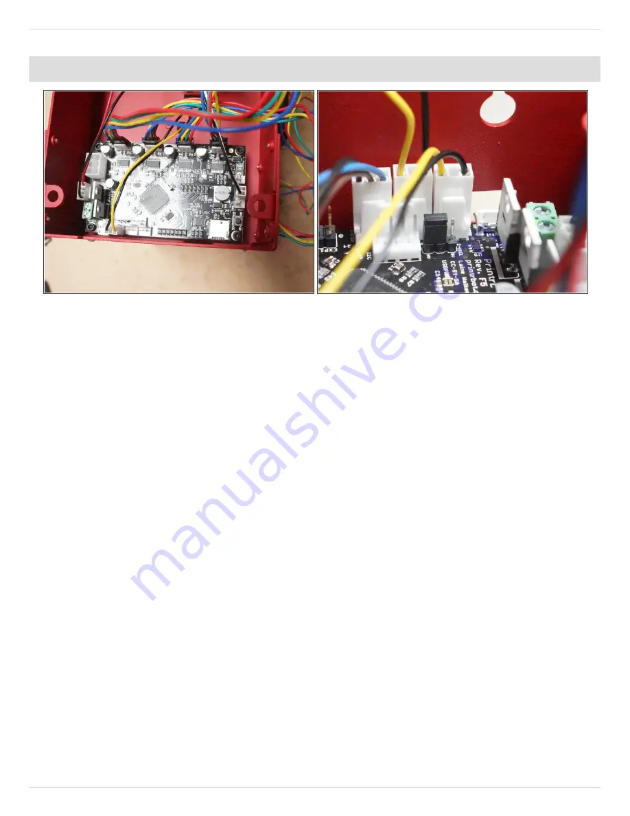
Motor connectors are not keyed so note the direction they are installed in the photos.
Other connectors are keyed and only plug in one way. The Extruder motor wire will be
shorter than the X motor wire.

X axis motor - "X-MOT" (blue, yellow, green, red)

Y axis motor - "Y-MOT" (blue, yellow, green, red)

Z axis motor - "Z-MOT" (blue, yellow, green, red)

Extruder motor - "E-MOT" (red, green, yellow, blue)

Fan ext - "FAN"

Hot End Power ext - "HOTEND"

Assembling the Printrbot Play Kit (Model 1505)

© 2015

help.printrbot.com

Page 24 of 29

Summary of Contents for Play 1505

Page 1: ...1505 Written By Printrbot Support TOOLS 1 Phillips Head Screwdriver 1 Zip tie gun 1 Blue Threadlocker 1 Micro Cutters 1 Needle nosed pliers 1 Rubber Mallet 1 Assembling the Printrbot Play Kit Model 15...

Page 2: ...the Bill of Materials and check it against what you received in your package If anything is missing please contact us at Printrbot com Support Docs If you are having a hard time with any of the exampl...

Page 3: ...you will need for this build CLICK HERE for printable files Step 3 Assembling Y Axis Idler Pulley Press one 624 bearing into a delrin pulley half Then repeat this step to make a second pressed bearin...

Page 4: ...screws x2 The metal switch of the end stop should be oriented to the outside of the base away from the bearing NOTE Be sure to use the end stop with the shortest wires TIP This will be your Y axis en...

Page 5: ...eight of the GT2 pulley on motor to align with the delrin pulley bearing stack assembled earlier Once you have found the correct GT2 pulley alignment use Threadlocker to secure the set screws on to th...

Page 6: ...s bar ends x2 onto both sides of the base with 4 20 3 8 plastite screws x3 each Step 7 Installing Z Axis Motor Mount your Printrboard with M3 6mm screws x4 Make sure the USB and SD Card slots are faci...

Page 7: ...rod The set screw will seat itself into the threads on the acme rod as it is tightened Try lifting up on the threaded rod to make sure it has been secured by the set screw REMINDER Use Threadlocker on...

Page 8: ...motor to the XZ carriage plate with M3 6mm screws x2 Note that motor is oriented with the wiring directed away from the XZ carriage plate TIP This will be your X axis motor Take a moment to label the...

Page 9: ...ling the 8mm bearings for the Z axis Step 13 Install X Axis Idler Pulley Press two 624 bearings into two Delrin pulley halves Place 1 8 nylon spacer between the bearing pulley Insert an M4 20mm screw...

Page 10: ...same side as the X axis motor opposite side of X idler pulley Use plastite screws x2 each to attach X axis bar clamps onto the bar ends and secure the bars to the XZ carriage plate Step 15 NOTE If you...

Page 11: ...with M2 5 10mm screws x2 NOTE The end stop switch should open towards the middle of the XZ carriage plate with the gator mouth open towards the X axis motor Step 17 Install Wire Relief and Position E...

Page 12: ...ime alternating between the 4 screws until all are tight Step 19 Install X Axis Belt Tensioner Thread the 500mm belt longer belt through the 2 holes in the belt tensioner as shown Zip tie close to the...

Page 13: ...Wrap the belt around X axis idler pulley Next route the belt around the GT2 pulley aligning the teeth of the belt with the grooves of the pulley Assembling the Printrbot Play Kit Model 1505 2015 help...

Page 14: ...nst the grooves of the belt NOTE Secure the zip tie as close to the extruder cart as possible Also make sure the nub of the zip tie is pointing away from the carriage Failure to do so could cause the...

Page 15: ...s motor with a E Step 23 Preparing Extruder Arm Thread an M3 30mm philips head screw through hole in extruder arm Add the extruder spring onto screw and secure with an M3 hex nut Place a 624 bearing i...

Page 16: ...dip in thread locker and secure the drive gear onto the motor shaft with set screw REMINDER Once the drive gear is aligned use Threadlocker to secure the set screw on to the motor shaft Place end of s...

Page 17: ...wired connector on the hot end Black red wiring cable extension connects to black wired connector on hot end Attach extension cables as advised in previous step Press hot end into matching hole on ext...

Page 18: ...ure the Auto Leveling Probe within the sensor probe clamp using the M3 16mm screw Tighten until the probe is secure Step 27 Extruder Wiring Tighten a zip tie around the extruder assembly wiring Any co...

Page 19: ...tie Use another zip tie to manage the wiring for the X axis motor wiring Step 29 Bend the wires in middle and pull all wires together through second wire wrap Stretch out the wrap to its full length a...

Page 20: ...Note that the fan wires are directed to the top of the fan shroud and the stickers for the fan are facing away from the front of the fan shroud Step 31 Attach Top Z Axis Bar Ends Use plastite screws x...

Page 21: ...ed end piece and thread them just slightly into the Y axis belt tensioner Feed the remaining GT2 belt into the belt tensioner Route the GT2 belt around the outside of the GT2 pulley and then back arou...

Page 22: ...he acme rod into the delrin acme nut Attach the top plate delrin Z rod bar end assembly to the printer by pushing the existing vertical smooth rods ends into the delrin pockets of the top plate Push t...

Page 23: ...dd the left side panel onto the bottom and top plates Secure the left panel to top panel with M3 6mm button head screws x6 using a 2mm allen hex key Next secure left panel to base panel using M3 6mm b...

Page 24: ...one way The Extruder motor wire will be shorter than the X motor wire X axis motor X MOT blue yellow green red Y axis motor Y MOT blue yellow green red Z axis motor Z MOT blue yellow green red Extrud...

Page 25: ...P Step 39 Plug the 6 pin connector of the power harness dongle into the Printrboard The barrell connector can be attached to the base by loosening the nut off of the threads and then tightening it bac...

Page 26: ...41 Modify Hotend Fan Extension Part 2 Pull the red wire out of molex connector Insert the freed red wire connector into slot next to black wire on the 4 pin white molex connector used by the hotend h...

Page 27: ...in ICSP pin closest to the edge of the board Make sure the black wire is connecting to the ICSP bottom left pin highlighted by green square Take note of the orientation of the molex connector when con...

Page 28: ...button head screws x2 to attach the shroud Click here to view a picture of this Step 45 Install Printer Feet and Power Connector Take a moment to manage the wiring under the base of the bot with zip...

Page 29: ...cate with your Printrbot Play Mac OS X Users Click here to download Cura 15 04 Windows Users Click here to download Cura 15 04 See Getting Started With Cura on Your Printrbot Play IMPORTANT FAILURE TO...

Reviews: