background image

210

PI-MAX

®

 4 System Manual

Issue 9

4.

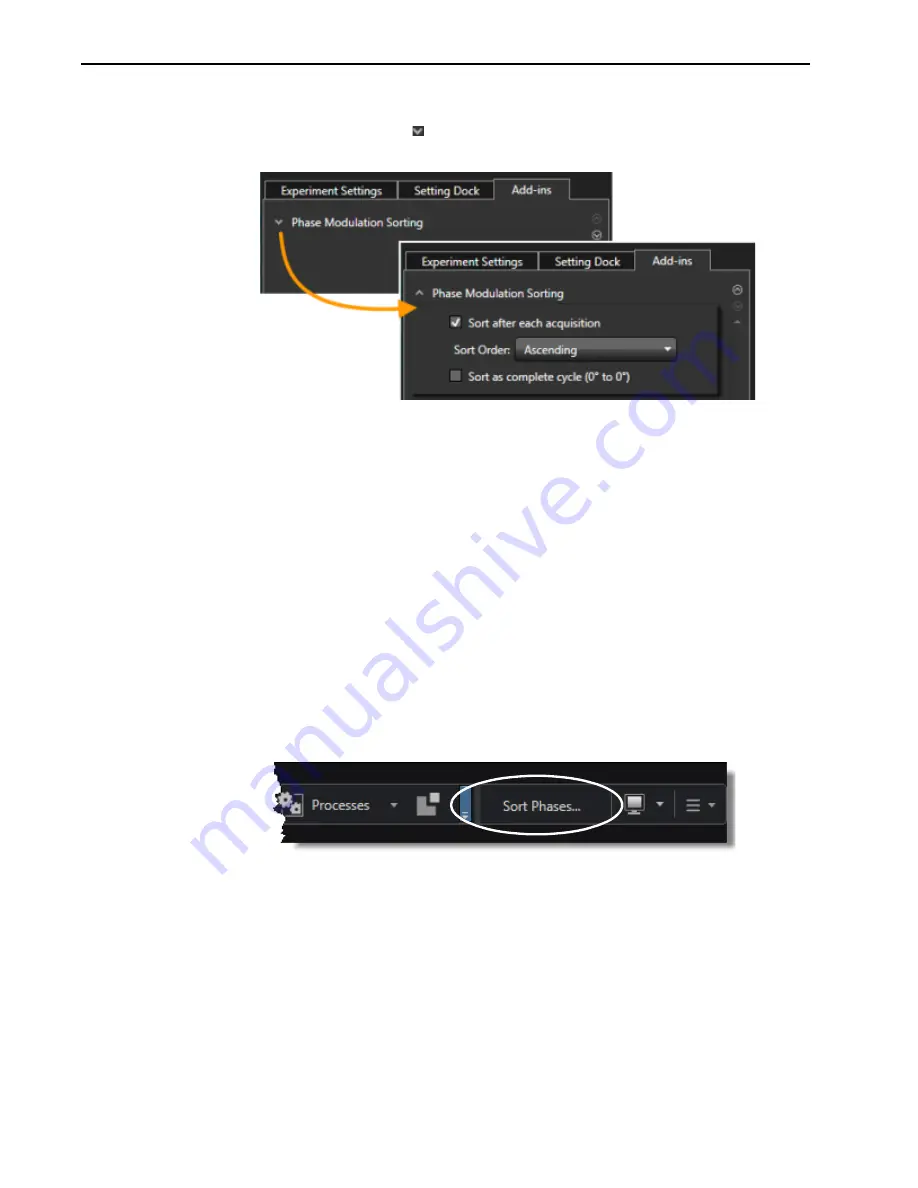
Perform the following procedure to sort SPE frames by phase after each acquisition:

a.

Click on the 

Add-ins

 tab and locate the 

Phase Modulation Sorting

 expander. If 

necessary, click on the   to expand it. See 

Figure 13-9

.

Figure 13-9: Typical Phase Modulation Sorting Add-in

b.

Check the box next to 

Sort after each acquisition

, and select the desired sort order 

from the pull-down list (i.e., 

Ascending

 or 

Descending

.)

c.

If desired, check the box next to 

Sort as Complete Cycle (0° to 0°.)

 When checked, 

alternate 0 degree Phases will be treated as 360 degree points.

d.

Perform the experiment as usual, and two SPE files are saved for each acquisition. 
For example, the two files from an experiment could be named:

2013 August 20 15_10_20.spe

This is the set of frames that have been sorted by Phase Modulation.

2013 August 20 15_10_20-unsorted.spe

This is the original set of frames.

5.

Perform the following procedure to sort SPE frames from a prior experiment:

a.

Within LightField, click on the 

Data

 tab.

b.

Locate and click on the 

Sort Phases…

 add-in button within the Data Toolbar. See 

Figure 13-10

.

Figure 13-10:Typical Phase Modulation Sorting Add-in Button: Data Toolbar

4411-

0139

_016

7

C

OLLAPSED

E

XPANDED

/O

PEN

4411

-013

9_016

8

Summary of Contents for PI-MAX4

Page 1: ...PI MAX4 Camera System 4411 0139 Issue 9 July 3 2018 ...

Page 2: ...History Sheet 1 of 2 Issue Date List of Changes Issue 9 July 3 2018 Issue 9 of this document incorporates the following changes Added Windows 8 1 and 10 as supported OS Issue 8 April 20 2016 Issue 8 of this document incorporates the following changes Removed the Declaration of Conformity Issue 7 March 14 2016 Issue 7 of this document incorporates the following changes Updated the following PI MAX4...

Page 3: ...D Specifications Issue 2 July 24 2013 Issue 2 of this document incorporates the following changes Added Chapter 14 PI MAX4 EM Family and other EM supporting information throughout the document Updated the Declarations of Conformity Issue 1 B February 11 2013 Issue 1 B of this document incorporates the following changes Editorial graphic and global nomenclature updates Issue 1 A February 27 2012 Th...

Page 4: ...4 PI MAX 4 System Manual Issue 9 This page is intentionally blank ...

Page 5: ... Chapter 2 System Installation 29 2 1 System Configuration Diagrams 31 Chapter 3 System Setup 33 3 1 Dangers and Warnings 33 3 2 Unpacking the System 33 3 3 Checking the Equipment and Parts Inventory 34 3 4 General System Requirements and Information 35 3 4 1 Ventilation 35 3 4 2 Power Specifications 35 3 4 3 Host Computer Specifications 36 3 4 3 1 WinX Host Computer Requirements 36 3 4 3 2 LightF...

Page 6: ...em On Off Sequences 62 5 3 Pre Exposure Removal of Accumulated Charge 63 5 3 1 Dark Charge 63 5 3 2 Cleaning 64 5 4 Phosphor Decay Delay 65 5 5 Temperature Control 66 5 5 1 Cooling Method 66 5 5 2 Necessary Cooling Precautions 67 5 5 3 Setting the Temperature 67 5 6 Exposure 68 5 6 1 Exposure with an Image Intensifier 68 5 6 1 1 Exposure Timing 68 5 6 2 Saturation 69 5 7 Background Subtraction 69 ...

Page 7: ...05 6 5 1 2 SyncMASTER1 Supplies the Master Clock 117 6 5 2 Single Shot Experiment 118 6 5 3 Swept Gate Experiment Variable Width Variable Delay 124 6 5 4 Static Gate Experiment Fixed Width Fixed Delay 124 Chapter 7 WinX and Gated Operation 125 7 1 Gating 125 7 2 Safety Precautions 126 7 2 1 Intensifier Mode 126 7 2 2 Alarms 127 7 3 Timing Mode 127 7 4 Micro Channel Plate MCP Bracket Pulsing 128 7 ...

Page 8: ...tion 168 9 7 Tips and Tricks 171 Chapter 10 WinX and Dual Image Feature 173 10 1 Requirements 173 10 2 Interline CCD Operation 173 10 3 Timing Modes 174 10 4 Configure a Single Trigger DIF Experiment 174 10 4 1 Hardware 174 10 4 2 Software 174 10 4 3 Operation 175 10 5 Configure a Dual Trigger DIF Experiment 180 10 5 1 Hardware 180 10 5 2 Software 180 10 5 3 Operation 180 10 6 Tips and Tricks 186 ...

Page 9: ...imal 221 14 1 2 2 Manual 221 14 2 Kinetics 224 14 2 1 Masking 224 14 2 2 Trigger Sources 226 14 2 3 Image Frame Acquisition 226 14 2 4 Data Readout 228 14 2 5 Binning 228 14 2 5 1 File Storage Conventions 231 14 2 6 Configuring Kinetics 232 14 2 7 Cleaning the CCD 233 14 2 8 Configuring a Kinetics Experiment 234 14 2 8 1 Configuring the Software Parameters 235 14 3 Photon Detection 236 14 3 1 Conf...

Page 10: ...F Out PI MAX4 1024i RF only 254 16 3 Gig E Ethernet Card 254 16 4 Extender Bracket Kit 254 16 5 CoolCUBEII Coolant Circulator Option 255 16 6 Spectrograph Option 255 16 7 Cables 255 16 8 Tubing 255 16 9 Application Software 256 16 10 User Manuals 257 Chapter 17 Troubleshooting 259 17 1 Alarm Sounds Repetitively 260 17 2 Alarm Sounds Sporadically 260 17 3 Baseline Signal Suddenly Changes by 1000 AD...

Page 11: ...d Terminology 287 C 2 LightField to WinX 289 Appendix D Extender Bracket Kit 291 Appendix E C and F Mount Information 293 E 1 C Mount Lens Information 293 E 1 1 Installation 293 E 1 2 Removal 293 E 2 F Mount Lens Adapter 294 E 2 1 Installation 294 E 2 2 Removal 294 E 3 Camera Orientation 295 E 4 Focusing C and F Mount Lenses 295 Appendix F Spectrograph Mount Information 297 F 1 Mount PI MAX4 to an...

Page 12: ...stem Components 19 Figure 1 2 Major Components of the Intensifier CCD 21 Figure 2 1 Typical PI MAX4 System Diagram 31 Figure 2 2 Typical PI MAX4 1024i RF System Diagram 31 Figure 3 1 Typical WinView 32 Setup Dialog 40 Figure 3 2 Typical LightField InstallShield Wizard Dialog 41 Figure 3 3 Typical CoolCUBEII Circulator 42 Figure 3 4 Typical WinX Camera Detection Wizard Dialog 44 Figure 4 1 LightFie...

Page 13: ...e 5 24 Typical Advanced Intensifier Dialog 91 Figure 5 25 Typical Region of Interest Expander 92 Figure 5 26 Typical Trigger Expander Internal Trigger Source Parameters 93 Figure 5 27 Typical Trigger Expander External Trigger Source Parameters 93 Figure 5 28 SuperSYNCHRO Timing Expander 94 Figure 6 1 Timing Diagram MCP Bracket Pulsing 100 Figure 6 2 Timing Diagram MCP Bracket Pulsing 103 Figure 6 ...

Page 14: ...7 Typical Sequential Gating Setup Dialog 142 Figure 7 18 Typical View Width Delay Sequence Dialog 143 Figure 7 19 Typical SuperSYNCHRO Dialog Trigger Out Tab 144 Figure 7 20 Experiment Setup Timing Tab 145 Figure 7 21 Experiment Setup Main Tab 145 Figure 7 22 Typical Experiment Results Shown in 3 D 146 Figure 7 23 Block Diagram SyncMASTER1 as Master Clock 147 Figure 7 24 Timing Diagram SyncMASTER1...

Page 15: ...ware Setup Dialog Controller Camera Tab 181 Figure 10 14 WinX Experiment Setup Dialog Main Tab 182 Figure 10 15 WinX Experiment Setup Dialog Timing Tab 183 Figure 10 16 WinX Pulsers Dialog 183 Figure 10 17 WinX SuperSYNCHRO Dialog Gating Tab 184 Figure 10 18 WinX DIF Gating Setup Dialog Dual Trigger 184 Figure 10 19 WinX SuperSYNCHRO Dialog Trigger In Tab 185 Figure 10 20 WinX SuperSYNCHRO Dialog ...

Page 16: ...l High Speed Camera Expander 238 Figure 14 21 Typical High Speed Camera Spectroscopy Settings 239 Figure 14 22 Typical High Speed Camera Imaging Settings 239 Figure 14 23 Typical Previous and Current Frame Rate Information 239 Figure 14 24 Typical Configuration Options Time Stamping Frame Tracking 240 Figure 16 1 PI MAX4 Rear Panel 250 Figure 16 2 PI MAX4 1024i RF Rear Panel 250 Figure 17 1 Camera...

Page 17: ...Internal Sync Information for Gated Operation 128 Table 7 2 Single Shot Experiment Time Budget 148 Table 12 1 Typical Picosecond Gating Information PI MAX4 1024i 192 Table 13 1 Phase Sweep Information for Sweep 360 206 Table 13 2 PI MAX4 1024i RF Connectors Indicators and Switches 213 Table 13 3 PI MAX4 1024i RF Power Supply Connectors Indicators and Switches 215 Table 14 1 Mask Window Sizes for 1...

Page 18: ...18 PI MAX 4 System Manual Issue 9 This page is intentionally blank ...

Page 19: ...match the PI MAX4 to the widest possible range of experimental requirements In operation data acquired by the camera is routed to the computer for processing and display The computer controls both the system configuration and data acquisition via software of which Princeton Instruments LightField and WinView 32 are examples Except where specifically noted the information within this system manual ...

Page 20: ...lectronics scan control and exposure timing hardware and controller I O connectors Readout modes supported include full resolution simultaneous multiple sub images and non uniform binning Single or multiple software defined regions of interest can also be tested without having to digitize all the pixels of the array Flexible exposure set through software is also fully supported The PI MAX4 contain...

Page 21: ...ons are attracted to more positively charged surfaces and are repelled by more negatively charged surfaces This principal is used to control electron flow through the intensifier tube changing the photocathode voltage with respect to the voltage at the MCP input is used to switch gate the intensifier on and off 1 Incident photons pass through the intensifier input window strike the photocathode an...

Page 22: ...to an analog voltage 8 This voltage is input to the selected analog to digital A D converter s where it is digitally encoded The conversion speed and the quality of the data are dependent on the effective ADC rate 9 The digitized information is transmitted from the camera through the Ethernet cable to the interface card in the host computer where it is stored in RAM 10 The application software ret...

Page 23: ...truments the protection provided by the equipment may be impaired 2 If the equipment is damaged the protective grounding could be disconnected Do not use damaged equipment until its safety has been verified by authorized personnel tampering with its operation is also prohibited Inspect the supplied power cord If it is not compatible with the power socket replace the cord with one that has suitable...

Page 24: ...continuously biased OFF and the intensifier is as safe as it can be NOTE In order for gating to occur the I I T switch on the back of the PI MAX4 must also be in the ON position 1 4 2 Audible Alarm To reduce the risk of camera damage the PI MAX4 camera is equipped with an audible alarm in the camera activated when the intensity of light falling on the image intensifier exceeds a preset threshold W...

Page 25: ...ination level has been lowered If the alarm sounds continuously even when the illumination level is adequately low shut the system down and contact the factory for guidance 1 5 Precautions To prevent permanently damaging the system please observe the following precautions Always switch off and unplug the PI MAX4 power supply before changing your system configuration in any way Whenever you turn th...

Page 26: ...ondensation on the array that could cause irreversible damage Such damage would not be covered by the Warranty Before a PI MAX4 camera leaves the factory its CCD chamber is backfilled with clean dry air or dry nitrogen For proper operation it is essential that the integrity of the front enclosure be maintained In normal operation the CCD chamber should remain sealed for the life of the camera and ...

Page 27: ...nd place it in operation Topics covered include a detailed description of the camera installation and setup first time data acquisition tips and tricks microscopy applications temperature control and more A brief description of each chapter and appendix is provided Chapter 1 Introduction provides an overview of the PI MAX4 camera Topics include a description theory of operation and specifications ...

Page 28: ...ndix B Outline Drawings includes outline drawings for the PI MAX4 camera the PI MAX4 power supply and the CoolCUBEII coolant circulator Appendix C WinX LightField Cross Reference includes two alphabetically sorted tables WinX to LightField and LightField to WinX that cross reference terms used in the two applications Appendix D Extender Bracket Kit explains how to use this kit to mount the PI MAX4...

Page 29: ...s drivers 5 If the application software has not already been installed on the host computer install it Section 3 6 Application Software Installation on page 39 WinView User Manual document number 4411 0046 WinSpec User Manual document number 4411 0048 LightField User Manual document number 4411 0125 6 With the PI MAX4 power supply and computer power turned OFF connect the Ethernet cable GigE to th...

Page 30: ...Manual document number 4411 0046 WinSpec User Manual document number 4411 0048 11 Verify the hardware setup information and if necessary edit the parameters Enter the pulser information Enter the experiment setup parameters If using a spectrograph enter or edit that setup information LightField User Manual document number 4411 0125 WinView User Manual document number 4411 0046 WinSpec User Manual ...

Page 31: ...h coolant circulator and dry nitrogen tank connections are optional 90 264 100 240 Power Supply Power Supply Spectrograph Acton SP2300i PI MAX4 USB Computer Trigger In GigE Dry Nitrogen Tank AUX I O Cable 4411 0097_0003 LASER Modulator 100 240 GiGE Trigger In Power Supply PI MAX4 1024i RF Computer USER RF OUT LASER POWER AUX POWER AUX I O Cable 4411 0097_0113 SPECTROGRAPH COOLANT CIRCULATOR AND DR...

Page 32: ...32 PI MAX 4 System Manual Issue 9 This page is intentionally blank ...

Page 33: ... overload condition being detected The PI MAX4 is equipped with an audible alarm and shutdown circuit to bias the photocathode OFF if excessive photocathode current is detected The circuit automatically resets and biases the photocathode back on after about 0 5 seconds The short term protection provided will not prevent intensifier damage if excessive light is allowed to continuously fall on the i...

Page 34: ...Computer Interface GigE Computer Provided by user WinView WinSpec or LightField CD User Manuals Note that the LightField manual is supplied on the LightField CD and will be installed in the program directory when the program is installed Interface Dependent Components Computer Interface GigE Cable Standard Ethernet Cable 6050 0621 5 meter Other lengths up to 100 m are available Interface Card User...

Page 35: ... Its purpose is simply to cool the power supply electronics This fan runs continuously whenever the power supply is powered Air enters the through ventilation openings in the side panels flows past the warm electronics and is drawn out the rear by the fan It is important that there be an adequate airflow for proper functioning As long as both the intake ventilation openings and the fan exhaust ope...

Page 36: ...ons 3 4 3 1 WinX Host Computer Requirements When running WinX data acquisition software the host computer must meet or exceed the following specifications 32 bit Operating System Windows XP SP3 or later Windows Vista or Windows 7 2 GHz Pentium 4 minimum 1 GB RAM minimum CD ROM drive At least one unused PCI card slot 32 bit PCI 2 3 compliant 32 bit 33 66 MHz bus Super VGA monitor and graphics card ...

Page 37: ... compliant 32 bit 33 66 MHz bus Super VGA monitor and graphics card Supporting at least 65535 colors with at least 128 Mbyte of memory NOTE Memory requirement is dependent on desired display resolution 10 000 RPM recommended hard disk with a minimum of 1 GB available space A complete LightField installation requires approximately 50 MB of space The remaining space is required for data storage and ...

Page 38: ...e case of cameras equipped with F mount do not mount the camera in the nose up operation where the lens mount would be required to hold the camera s weight The F mount is not designed to sustain the weight of the camera in this orientation and the camera could pull free You must provide additional support for the camera Should the camera be mounted in the nose up position beneath a table take care...

Page 39: ...allation procedure for WinX application software NOTES 1 Install the GigE Adapter card BEFORE installing the WinView 32 or WinSpec 32 application software 2 The interface cable should remain disconnected from the camera until after WinView 32 or WinSpec 32 version 2 5 25 or higher has been successfully installed Perform the following procedure to install WinX on the host computer 1 Insert the WinV...

Page 40: ...w on screen prompts 4 Once the installation has been completed connect the camera to the host computer and turn on the camera s power supply 5 Reboot the host computer Windows will automatically detect the newly installed GigE card REFERENCES For additional information refer to Section 4 6 WinX First Light Instructions on page 55 4411 0139_0005 ...

Page 41: ...red for product activation Perform the following procedure to install LightField on the host computer 1 Insert the LightField Installation CD into the CD drive on the host computer and follow the on screen prompts Figure 3 2 illustrates a typical InstallShield Wizard dialog Figure 3 2 Typical LightField InstallShield Wizard Dialog 2 After the installation has been completed reboot the computer 3 C...

Page 42: ... 10 feet 3 m Typically the camera is at table height and the circulator is on the floor 3 Make the coolant connections between the circulator and the camera It does not matter which hose from the circulator is plugged into a coolant port on the camera 4 It is recommended that hoses be secured to the camera hose barbs with the clamp supplied NOTES 1 Verify that there are no kinks in the hoses that ...

Page 43: ...n soda are common in the CoolCUBEII particularly following start up and do not prevent proper operation If there are no problems proceed to step 9 If leaks or large air bubbles are observed turn the circulator off and correct the problem s by securing the hoses or adding more coolant to the reservoir Turn the circulator back on Recheck and if there are no problems proceed to step 9 9 Turn the came...

Page 44: ...st 32 has been installed with a supported camera If simply installing a new camera type click on the Launch Camera Detection Wizard button on the Controller CCD tab to launch the wizard 3 When the Welcome dialog is displayed the check box should remain unchecked Click Next See Figure 3 4 Figure 3 4 Typical WinX Camera Detection Wizard Dialog 4 Follow the on screen prompts to perform the initial ha...

Page 45: ...urned on 2 Launch LightField 3 As LightField is launching it will detect all available devices and automatically load appropriate icons into the Available Devices area of the Experiment workspace 4 When an icon is dragged into the Experiment Devices area appropriate expanders will be loaded into the Experiment Settings stack on the left hand side of the window NOTE For step by step procedures desc...

Page 46: ...46 PI MAX 4 System Manual Issue 9 This page is intentionally blank ...

Page 47: ...opriate chapters 4 1 Required Equipment and Cables The equipment and cables listed below are required to set up and run the PI MAX4 camera system in accordance with the procedures described in this chapter Princeton Instruments PI MAX4 camera with C mount adapter User supplied C mount lens with smallest aperture of f 16 or f 22 PI MAX4 power supply Computer equipped with a GigE Ethernet interface ...

Page 48: ...s in front of the camera 4 4 Turning on the System WARNING Always begin with the lens stopped all the way down largest f stop number to minimize the risk of overloading the intensifier Perform the following procedure to turn on a PI MAX4 system 1 Turn on the PI MAX4 power supply NOTE The PI MAX4 overload alarm may sound briefly and then stop This is normal and is not a cause for concern However if...

Page 49: ... The following procedure assumes The system has been set up in accordance with the instructions in the previous chapters Previous sections of this chapter have been read Familiarity with the LightField application software The system is being operated in imaging mode The target is a sharp image text or a drawing that can be used to verify that the camera is seeing and can be used to maximize focus...

Page 50: ...tware is assumed If this is not the case review the software manual or have it available while performing this procedure 1 Once LightField has launched an icon representing the camera should be visible within the Available Devices area For example in Figure 4 1 a PI MAX4 1024i is shown Figure 4 1 LightField Desktop Available Devices 4411 0139_0017 ...

Page 51: ... for the camera are provided Within the Status bar are two icons which provide real time temperature and intensifier status information The Temperature status section reports the current temperature for the system and whether the set temperature has been reached The Intensifier status icon indicates if the I I T Power switch located on the rear of the camera is turned on and if the Enable Intensif...

Page 52: ... 1 Verify that the I I T Power switch on the rear of the camera is in the ON position 2 Verify that Enable Intensifier is selected on the Common Acquisition Settings expander 3 Click on the View tab located just above Available Devices to change to the display area See Figure 4 3 Figure 4 3 LightField Desktop View Area 4411 0139_0019 ...

Page 53: ...ure the Gating parameters as desired The list of configuration parameters varies depending on the specific Mode selected Refer to Table 4 1 Table 4 1 Configuration Parameters by Mode Repetitive Sequential Gate Delay Gate Width AUX Output Delay AUX Output Width Gate Delay Gate Width AUX Output Delay AUX Output Width Ending Gate Delay Ending Gate Width 4411 0139_0078 ...

Page 54: ... focus has changed If the image is upside down change the image orientation using the Online Corrections expander Figure 4 5 shows a properly oriented in focus image Figure 4 5 LightField View Area Displaying an Acquired Image 4 5 5 Focusing REFERENCES For complete information about focusing the PI MAX4 camera when using C F or spectroscopy mounts refer to Section E 4 Focusing C and F Mount Lenses...

Page 55: ... Previous sections of this chapter have been read Familiarity with the WinX application software The system is being operated in imaging mode The target is a sharp image text or a drawing that can be used to verify that the camera is seeing and can be used to maximize focus 4 6 2 Getting Started Prior to performing any procedure within this chapter Verify that a test target has been positioned app...

Page 56: ...layed as shown in Figure 4 7 Figure 4 7 Typical SuperSYNCHRO Dialog Trigger In Tab 3 On the Trigger In tab verify the following settings Internal is selected Frequency 10000 Hz 4 Click on the Gating tab Configure the Gating Mode by selecting Repetitive See Figure 4 8 Figure 4 8 Typical SuperSYNCHRO Dialog Gating Tab 4411 0139_0010 4411 0139_0011 ...

Page 57: ...following settings Gate Width 50 ms Gate Delay 10 ns Gates per Exposure 1 Repeat Width Delay 1 7 Click OK to save the Repetitive Gating configuration settings and return to the SuperSYNCHRO dialog 8 Click OK to save the SuperSYNCHRO configuration 9 From the Acquisition pull down menu select Experiment Setup The Experiment Setup dialog is displayed with the Main tab shown 4411 0139_0012 ...

Page 58: ...ate Mode Selected See Figure 4 10 Figure 4 10 Typical Experiment Setup Dialog Main Tab 11 Click on the ADC tab 12 From the Rate pull down list of camera specific frequencies select a frequency that is closest to mid range See Figure 4 11 Figure 4 11 Typical Experiment Setup Dialog ADC Tab 4411 0139_0013 4411 0139_0014 ...

Page 59: ... to begin initial data acquisition for a test image NOTE When using a C mount lens a PI MAX4 will typically focus on an object at distance of approximately 9 inches 22 86 cm 1 Verify that room or ambient lighting is subdued 2 Turn on the PI MAX4 I I T NOTE The PI MAX4 overload alarm may sound briefly and then stop This is normal and is not a cause for concern However if the alarm sounds repetitive...

Page 60: ...nd then try again to acquire a test image See Figure 4 13 for a sample image Figure 4 13 Sample Acquired Test Image 4 Once it has been confirmed that the PI MAX4 is able to acquire images turn the PI MAX4 I I T switch OFF and close WinX NOTE If the PI MAX4 will not be used with the lens replace the C mount lens with the screw in dust cover provided with the C mount adapter If a different adapter w...

Page 61: ...ge Clean cycles Continuous cleans Exposure modes Readout Digitization Software binning and Background subtraction Factors which pertain to a specific intensifier mode and pulser are described in the appropriate chapter 5 1 Data Acquisition Sequence When data is acquired the CCD array is exposed to an incoming signal which is then integrated on the array At the end of the exposure may include multi...

Page 62: ...the power supply and reopen the WinX application software before you can set up experiments and acquire new data 2 The WinX application software must be closed before turning off the power supply If you turn off the power supply before closing the WinX application software the communication link with the PI MAX4 will be broken You can operate the program in a playback mode i e examine previously a...

Page 63: ...d any signal that has integrated on the PI MAX4 array while it is waiting for a Start Acquisition command from the host computer After the Start Acquisition command is received a final clean cycle occurs and exposure begins During the exposure both the signal of interest and dark charge integrate on the array The longer the exposure and the warmer the camera the larger and less uniform the dark ch...

Page 64: ... to cleaning Number of Cleans Clean Cycles value is usually set to one 1 These are additional clean cycles that can be required after a start exposure signal is received and the current clean cycle has finished The maximum value for this entry depends on the camera Number of Strips per Clean Clean Cycle Height sets the number of rows that will be shifted and discarded per clean cycle While a large...

Page 65: ...shed Number of Cleans is defined on the Setup Hardware Cleans Skips tab Sensor Cleaning fly out pane on Sensor expander If you enter a value other than 0 you will further delay the start of the exposure by that number of clean cycles 5 4 Phosphor Decay Delay The WinX and LightField applications allow a delay between the end of the exposure time and the beginning of the array readout to be specifie...

Page 66: ...eltier device is then removed by the air drawn into the camera by the internal fans and exhausted through the side panel grill The fans are always running and cooling the CCD and the internal electronics Additional heat removal can be performed by circulating coolant through an internal heat block Air cooling With air cooling alone at an ambient temperature of 25 C temperature lock at 25 should ty...

Page 67: ... where the humidity is low enough to prevent internal condensation If the coolant is below the freezing temperature of water use a mixture of 50 water and 50 ethylene glycol as the coolant The easiest and most practical way to achieve the required low humidity is to put the PI MAX4 inside a closed container and purge the container with a continuous flow of dry air The air must be dry enough to hav...

Page 68: ...e light and the CCD is used for readout The exposure programmed by software in this case refers to duration of gating of the intensifier The intensifier s Micro Channel Plate MCP is composed of more than 106 individual miniature electron multipliers with excellent input to output spatial geometric accuracy Intensifier gain is varied by adjusting the voltage across the MCP or the voltage across the...

Page 69: ...re time There is however a maximum time limit for on chip averaging determined by either the saturation of the CCD pixels by the signal or the loss of dynamic range due to the buildup of dark charge in the pixels 5 7 Background Subtraction Each CCD has its own dark charge pattern or background that can be subtracted from the total acquired signal By subtracting this background you can eliminate th...

Page 70: ...nd digitized Depending on the experiment design binning may also occur as part of the readout operation For the PI MAX4 1024i camera and WinX dual port readout mode is selected whenever full image readout is selected or when the region of interest ROI is defined to be horizontally symmetrical and centered Single port readout is activated when the ROI is not horizontally symmetrical and centered Th...

Page 71: ...egins Non overlapped operation is automatically selected when the configured exposure time is shorter than the required readout time This process has been divided into four steps 1 Figure 5 6 illustrates the array early in the exposure cycle The imaging areas contain charge proportional to the amount of light integrated on each of them The masked storage areas are empty because no charge has been ...

Page 72: ...ere to the output node and off of the array for further processing The process continues until all charges have been completely transferred out of the array The image intensifier is off during this time so no signal charge is accumulated but dark current does accumulate Because this scheme is less time efficient than that used in the overlapped mode the frame rate may be lower in non overlapped op...

Page 73: ...Overlapped End of Readout NOTE A subsection of the CCD can be read out at full resolution sometimes increasing the readout rate while retaining the highest resolution in the region of interest ROI 3 Charge from first pixel has been shifted to the Output Node A1 B1 C1 A2 B2 A4 A3 B4 B3 A6 A5 B6 B5 C2 C4 C3 C6 C5 D2 D4 D3 D6 D5 D1 4411 0139_0028 4 After first image is read out masked areas are empty...

Page 74: ... shift register is a single line of pixels along the edge of the CCD not sensitive to light and used for readout only Typically the shift register pixels hold twice as much charge as the pixels in the imaging area of the CCD After the first row is moved into the shift register the charge now in the shift register is shifted toward the output node located at one end of the shift register As each va...

Page 75: ...smaller dimension of the CCD Ny is the larger dimension of the CCD tsr is the time needed to shift one pixel out of the shift register tv is the time needed to digitize a pixel ti is the time needed to shift one line into the shift register A subsection of the CCD number of horizontal pixels must be divisible by 4 can be read out at full resolution sometimes dramatically increasing the readout rat...

Page 76: ...n the Edit ROIs button and creating a custom ROI with Bin W and the Bin H values of 2 Limitations of hardware binning include Lowered resolution because charge from adjacent pixels is summed into a super pixel Increased possibility to blooming Because shift register pixels typically hold only twice as much charge as image pixels the binning of large sections may result in saturation and spilling o...

Page 77: ...the CCD In LightField single port readout is configured with the Readout Ports Used configuration setting located on theAnalog to Digital Conversion expander Full Frame Binning Figure 5 11 shows an example of 2 x 2 binning with dual port operation for an interline array Each pixel of the image displayed by the software represents 4 pixels of the array Figure 5 11 Dual Port Readout 2 2 Binning of I...

Page 78: ...xample of single port operation for a full frame array Figure 5 13 Single Port Readout 2 2 Binning of Full Frame CCD 4411 0139_0032 A1 B1 C1 D1 A2 B2 C2 D2 A3 B3 C3 D3 A4 B4 C4 D4 A5 B5 C5 D5 A6 B6 C6 D6 A3 B3 C3 D3 A4 B4 C4 D4 A5 B5 C5 D5 A6 B6 C6 D6 A1 B1 C1 D1 A2 B2 C2 D2 A3 B3 C3 D3 A4 B4 C4 D4 A5 B5 C5 D5 A6 B6 C6 D6 A1 B1 C1 D1 A2 B2 C2 D2 A3 B3 C3 D3 A4 B4 C4 D4 A5 B5 C5 D5 A6 B6 C6 D6 C1 D...

Page 79: ...o End 200 pixels no grouping binning Since 200 4 50 this is a valid ROI setup X Start to End 200 pixels and grouping binning is by 8 The resulting number of super pixels is 25 Since 25 4 6 25 this is not a valid ROI setting for the horizontal direction X Start to End 240 pixels no grouping binning Since 240 4 60 this is a valid ROI setup X Start to End 240 pixels and grouping binning is by 3 The r...

Page 80: ...ot centered horizontally an Experiment Conflict is shown Left clicking on the icon displays a pop up window in which detailed information about the conflict is provided In this instance the ROI needs to be centered horizontally To center the ROI left click on the icon near the top of the window to reposition the ROI correctly NOTE Only one ROI may be created when Dual Port readout has been selecte...

Page 81: ... would permit even division by those values If you use the Full Sensor Binned function LightField creates the appropriately sized ROI and reports the resulting image size The Custom Region s of Interest panel shows the non binned ROI size and the bin values that will be applied to it Empty Readout Register Exposure has ended and image has been shifted to masked area of each pixel Charges from two ...

Page 82: ...m the raw data is necessary Software binning is also useful in high light level experiments where the camera is again photon shot noise limited Summing multiple pixels in software corresponds to collecting more photons and results in a better S N ratio in the measurement In LightField and WinX software software binning can be configured to occur automatically or as a manual post processing operati...

Page 83: ...signals more electrons are required per ADU Since binning combines the signal from two or more pixels the user may also want to select 1 Low if binning is being applied In both instances the goal is to prevent CCD saturation and maximize signal acquisition 2 High Users who consistently measure low level signals may wish to select 2 High which requires fewer electrons to generate an ADU and reduces...

Page 84: ... Acquiring After a start acquisition command this output changes state on completion of the array cleaning cycles that precede the first exposure Initially low it goes high to mark the beginning of the first exposure In Focus mode operation it remains high until the system is halted If a specific number of frames have been programmed it remains high until all have been taken and then returns low F...

Page 85: ...and can be used to drive an external electro mechanical shutter Contact the factory for more information Wait for Trigger Waiting For Trigger This level is at a logic high when the camera is ready to acquire and is waiting for an external trigger through the EXT SYNC connector before exposing the CCD The level goes low when a trigger is detected exposure begins The Wait for Trigger WFT signal goes...

Page 86: ...llect and store in a single file Each frame will be digitized and stored but all of the frames will be in a single file A frame may contain data from more than one region of interest as defined via the ROI Setup tab If the Accumulations 1 each stored frame will contain summed data sets from two or more exposures The number of separate frames stored will the same as it would be for Accumulations 1 ...

Page 87: ... then be incrementally increased until optimal results have been obtained NOTE The intensifier gain also affects the Equivalent Background Illumination EBI of the intensifier One side result of this is that in order to properly perform background subtraction a new background must be taken whenever the intensifier gain has been changed Intensifier Mode The Intensifier Mode selection configures the ...

Page 88: ... will interrupt the acquisition flow to process each frame as it is received Figure 5 22 compares the two modes NOTE The Safe Mode parameter found on the Timing tab is not the same as the Intensifier Safe Mode found on the Main tab Figure 5 22 Fast Mode Slow Mode Flow Charts Stop acquisition command sent from computer to camera Background or flatfield on Background and or flatfield correction perf...

Page 89: ...the most current image displayed on the screen It is also useful when data collection must be coordinated with external devices such as external shutters and filter wheels As seen in Figure 5 22 the computer controls when each frame is taken After each frame is received the camera issue a Stop Acquisition command to the camera instructing it to stop acquisition Once that frame has been completely ...

Page 90: ...ers are loaded in the Experiment Settings stack If this is the first time LightField has been launched with this specific camera the default settings for the camera will have been loaded into the expanders The following sections provide brief descriptions of many Experiment Settings expanders REFERENCES For detailed information about each expander refer to the LightField online help 5 14 1 Common ...

Page 91: ...ensifier Enable Intensifier When checked the Intensifier is enabled Intensifier Gain Configures the level of Intensifier Gain Advanced Intensifier Figure 5 24 illustrates a typical Advanced Intensifier dialog Figure 5 24 Typical Advanced Intensifier Dialog The following advanced parameters are configured on this dialog Phosphor Decay Delay Phosphor Decay Resolution Time Stamping Configures which i...

Page 92: ...terest Hardware or software binning are configured on this expander The Advanced button opens a fly out panel where the type of binning hardware or software to be used is configured when bin values other than 1 have been specified The Edit ROIs button opens the Edit Regions of Interest window where a reference image can be captured to help define which area or areas on the sensor are to be include...

Page 93: ...ger Frequency that has been selected on the SuperSYNCHRO Timing expander Refer to Section 5 14 4 SuperSYNCHRO Timing Expander for additional information External Figure 5 27 illustrates typical configuration parameters for External triggering Figure 5 27 Typical Trigger Expander External Trigger Source Parameters External triggering requires that an external trigger be defined so LightField will b...

Page 94: ...located at the bottom of the LightField desktop See Figure 5 28 NOTE The top of the SuperSYNCHRO Timing expander can be Dragged up to view more of the SuperSYNCHRO panel Dragged down to view more of the Experiment Settings stack or the Device View panel Figure 5 28 SuperSYNCHRO Timing Expander 4411 0139_0078 ...

Page 95: ...e Width AUX Output Delay AUX Output Width When Internal Trigger is the selected Trigger Source or SyncMASTER is turned on the Internal Trigger Frequency can also be configured Hyperlinks are also provided which open the appropriate expanders for quick access to configuration settings for Intensifier Trigger Phosphor Decay Delay Number of Frames On CCD Accumulations Readout Mode ...

Page 96: ...96 PI MAX 4 System Manual Issue 9 This page is intentionally blank ...

Page 97: ...s during the laser pulse thus reducing the flame emission interference by approximately the measurement duty factor ratio Exposure time is the time space from which charge integrating on the CCD will get summed into the reported data Gate width is the time during which light will be detected by the intensifier intensified and applied to the CCD Basically the intensifier controls what the chip sees...

Page 98: ...enabled disabled on the Common Acquisition Settings expander When the intensifier is enabled the camera can be gated When the intensifier is disabled the photocathode is continuously biased OFF and the intenser is as safe as it can be NOTE In order for gating to occur the I I T switch on the back of the PI MAX4 must be in the ON position 6 2 2 Alarms NOTE It is normal for an alarm to sound briefly...

Page 99: ...Table 6 1 for additional Internal Sync information when using Gated mode NOTE The Accumulations and Images or Spectra parameters WinView 32 or WinSpec 32 Acquisition Setup Main tab determine how data will be processed Integrating multiple events on the CCD really brings the power of the PI MAX4 to bear on low light gate mode experiments If the experiment allows many pulses can be summed on the CCD...

Page 100: ...of a camera with conventional photocathode only gating to perform certain kinds of measurements in the UV is adversely affected MCP bracket pulsing1 keeps the MCP biased OFF except for an interval that brackets the timing of the photocathode gate as shown in Figure 6 1 Figure 6 1 Timing Diagram MCP Bracket Pulsing For emitted photoelectrons to be accelerated in the MCP the MCP must be biased ON In...

Page 101: ... the specific nanosecond scale time slice to be observed within the much longer probe flash In these absorbance experiments accurate measurement of absorbance values depends critically on the lack of stray light contamination particularly at moderate to high optical density levels Selecting a 5 ns time window out of a 10 µs pulse is already one part in 2 000 If UV leakage gives an on off ratio of ...

Page 102: ... ratio 16 000 close to the non bracket value Note that background light need not be the limiting factor in measurements where MCP bracket pulsing is unable to provide the required degree of rejection In such measurements the option remains of installing an external shutter ahead of the PI MAX4 6 4 4 Impact of Bracket Pulsing on Delay If operating in the UV when bracket pulsing is activated Gen II ...

Page 103: ...tion delay between Trigger In and T0 is approximately 12 ns and the insertion delay between Trigger In and Photocathode Gating is 35 ns NOTE The minimum delay between Trigger In and Photocathode Gating in bracket mode is 35 ns in order to allow the MCP to achieve full gain before the photocathode is gated on Bracket Aux Out 12 ns Ů PU PU Trigger In T0 T0 remains high for the duration of the pulse ...

Page 104: ...intensity vs time such as might be obtained with a sampling oscilloscope This technique is used to measure lifetime decays Repetitive Sequential 2 The Trigger is repetitive and Gate Width and Delay are varied over the course of the measurement Gate Width and Delay can be incremented in a linear fashion or in an exponential fashion Increasing the Gate Width is useful for trying to find fine detail ...

Page 105: ... Fixed Width Variable Delay Section 6 5 2 Single Shot Experiment Section 6 5 3 Swept Gate Experiment Variable Width Variable Delay Section 6 5 4 Static Gate Experiment Fixed Width Fixed Delay 6 5 1 Swept Gate Experiment Fixed Width Variable Delay This experiment is an attempt to time resolve a Xenon light flash from a commercially available strobe light 6 5 1 1 Experiment Supplies the Master Clock...

Page 106: ...mperature Setpoint See Figure 6 5 Figure 6 5 Typical Sensor Expander Computer 110 220 96 264 Trigger In GigE Power Supply PI MAX4 USB Spectrograph Photodiode Photocathode Gating Off 12 nS On Off Off On Off MCP Gating AUX Out Level changes for T0 depend on the pulse sequence s defined by the user Delay is programmable MCP Gating Photocathode Gating T0 remains high for the duration of the pulse ense...

Page 107: ... to configure the desired cleaning parameters See Figure 6 6 Figure 6 6 Typical Sensor Cleaning Dialog If a Restore to Default button is displayed on the dialog click it to restore the associated parameter to its default value See Figure 6 7 Figure 6 7 Typical Reset to Default 4411 0139_0070 4411 0139_0185 ...

Page 108: ...es area When the spectrograph icon is dragged into the Experiment Devices area the Spectrometer expander is added to the Experiment Settings stack with appropriate parameters provided See Figure 6 8 for typical expanders Figure 6 8 Typical Spectrometer Expanders 6 Move the grating to the desired wavelength ACTON SPECTRAPRO 4411 0139_0071 SERIES SPECTROGRAPH 4411 0139_0071 4411 0139_0186 LS785 SPEC...

Page 109: ... operating and is properly focused by running it in Internal Trigger mode Perform the following procedure to run in Internal Trigger mode to verify camera focus a On the Common Acquisition Settings expander within the Intensifier section configure the following parameters Enable Intensifier check the associated box Intensifier Gain Enter a value between 1 and 100 inclusive See Figure 6 10 4411 013...

Page 110: ...Typical Common Acquisition Settings Expander b On the Analog to Digital Conversion expander configure the following parameters Speed Analog Gain See Figure 6 11 Figure 6 11 Typical Analog to Digital Conversion Expander 4411 0139_0042 4411 0139_0074 ...

Page 111: ... Adjust the light level as required e If necessary click on the View tab and then click Run The camera will begin acquiring data NOTE Data collected at this time will not be saved f Once it has been verified that the camera is operating properly and is in focus halt data acquisition 9 On the Regions of Interest expander configure the following parameters as indicated Select Full Sensor Binned Bin ...

Page 112: ... Regions of Interest Expander Full Sensor Binned 10 On the Trigger expander configure the following Trigger In parameters as indicated Source External Threshold 1 5 Coupling DC Termination 50 Trigger Determined By Rising Edge See Figure 6 14 4411 0139_0076 ...

Page 113: ...er 6 LightField and Gated Operation 113 Figure 6 14 Trigger Expander External Trigger Source Configuration 11 Open the SuperSYNCHRO Timing expander located above the Status bar See Figure 6 15 4411 0139_0077 ...

Page 114: ...following procedure to configure the pulse sequence Click on the Frames to Save hyperlink Enter the number of frames to be acquired e g 41 for this experiment Configure the Starting Gate Width and Ending Gate Width Because this experiment requires a fixed gate width these values will be the same Starting Gate Delay 1 s Ending Gate Delay 201 s Click on the On CCD Accumulations hyperlink Enter the n...

Page 115: ...nnector will be at the frequency specified on the Internal Trigger Frequency field The output of the SyncMASTER2 connector will be at the same frequency as that of SyncMASTER1 However a delay can be specified so the edges of SyncMASTER2 will occur after the edges of SyncMASTER1 When using the AUX Output signal from the SuperSYNCHRO to trigger a piece of equipment enter the Auxiliary pulse delay ti...

Page 116: ...on only for the time that each gate pulse is applied This limits the risk of damage resulting from room light However there is a risk of damaging overload from intense light sources such as lasers 14 Figure 6 17 illustrates the graph for a Sequential Repetitive experiment with fixed width and variable delay Show Frame Cross Section has been selected The intensity of the selected point was at it ma...

Page 117: ...ER1 BNC and the light source i e experiment for triggering the event See Figure 6 18 Figure 6 18 Block Diagram SyncMASTER1 as Master Clock Figure 6 19 illustrates the timing diagram for this experiment configuration Figure 6 19 Timing Diagram SyncMASTER1 as Master Clock PI MAX4 Spectrograph AUX I O AUX OUT 96 264 GigE USB AUX I O Cable SynchMASTER1 Out 4411 0139_0062 SyncMASTER1 Out SyncMASTER1 Ou...

Page 118: ...e accumulation while it waits for the trigger This experiment is an attempt to capture a 60 ns fluorescence generated by a single shot laser The time budget of the experiment is detailed in Table 6 2 This information is important in order to choose the correct length fiber optic cable In this experiment cable lengths are kept to a minimum so that the length of the fiber optic cable required may al...

Page 119: ...NOTE If PI MAX4 has to wait more than a few seconds for an external trigger it is advisable to increase the number of cleans Figure 6 21 Cleaning Cycles Cleaning and Skipping Expander The sequence of operations is similar to that for Sequential experiments After focusing the camera on the fluorescing sample an appropriate Gain is configured See Figure 6 22 4411 0139_0070 ...

Page 120: ...ommon Acquisition Settings Expander Intensifier Gain Gate Width and Gate Delay should be configured so that the intensifier is gated ON during the entire event For example in this case the event is a 60 ns fluorescence See Figure 6 23 4411 0139_0042 ...

Page 121: ...Chapter 6 LightField and Gated Operation 121 Figure 6 23 Typical Repetitive Gating Setup 100 ns Width 25 ns Delay 4411 0139_0082 ...

Page 122: ...122 PI MAX 4 System Manual Issue 9 Figure 6 24 shows the result of this experiment Figure 6 24 Single Shot Result Fluorescence Spot Width 100 ns Delay 10 ns 4411 0139_0083 ...

Page 123: ...ation 123 Figure 6 25 shows the peak obtained by binning the entire region around the fluorescence spot in the vertical direction Figure 6 25 Single Shot Result Fluorescence Spot Width 100 ns Delay 10 ns Binned Vertically 4411 0139_0084 ...

Page 124: ...not equal Ending Gate Width value Refer to Section 6 5 3 Swept Gate Experiment Variable Width Variable Delay for additional information 6 5 4 Static Gate Experiment Fixed Width Fixed Delay The procedure for conducting a Static Gate experiment is similar to that for conducting a Swept Gate experiment with the following parameter configuration changes Gate Mode Repetitive Gate Width and Gate Delay m...

Page 125: ...uring the laser pulse thus reducing the flame emission interference by approximately the measurement duty factor ratio Exposure time is the time space from which charge integrating on the CCD will get summed into the reported data Gate width is the time during which light will be detected by the intensifier intensified and applied to the CCD Basically the intensifier controls what the chip sees du...

Page 126: ...ately turn the I I T switch on the back of the PI MAX4 to the OFF position Cover the camera s window and only after the illumination level has been lowered to safe operating conditions can the I I T switch be turned ON 7 2 1 Intensifier Mode The PI MAX4 can operate in one of two intensifier modes Gate Mode The photocathode is biased on only for the time that each gate pulse is applied As a result ...

Page 127: ...CAUTION Discontinue operation and contact the factory at once if sporadic or continuous unwarranted alarms occur They may indicate intensifier damage or another situation that requires immediate attention 7 3 Timing Mode In Gate Mode the internal timing generator uses Internal Sync timing which initiates a readout cycle following each internally generated timing pulse sequence 1 Internal handshake...

Page 128: ...ithin the visible spectrum the on off ratio of a typical Gen II Intensifier with just the photocathode gated is excellent typically between 106 and 107 For most measurements this ratio is more than adequate to guarantee that any signal reaching the CCD during intensifier Off times is too small to affect the data However when working with wavelengths below 350 nm optical leakage through the photoca...

Page 129: ...robe lasers Atomic emission from flames also has significant UV content If the flame is continuous the UV background will also be continuous Even where a flame is transient e g internal combustion engine its lifetime can be many milliseconds compared to the nanosecond time scale of the laser used This background can be a million times as long If the background is bright then a UV on off ratio of 2...

Page 130: ...e PI MAX4 Electrically gating the MCP will only reduce leakage at wavelengths where the MCP has photoelectric response primarily in the UV Thus for visible and NIR wavelengths where leakage is primarily optical the improvement will be minimal although the on off ratio is already very good in these regions Note that in some spectroscopic applications visible leakage may appear to be reduced by MCP ...

Page 131: ...is enabled by selecting Bracket Pulsing ON from within the host software Figure 7 2 illustrates the timing diagram for bracket pulsing NOTE Because Gen III Intensifiers do not respond in the UV bracket pulsing is not available for these intensifiers Figure 7 2 Timing Diagram MCP Bracket Pulsing As shown in Figure 7 2 the insertion delay between Trigger In and T0 is approximately 12 ns and the inse...

Page 132: ...intensity vs time such as might be obtained with a sampling oscilloscope This technique is used to measure lifetime decays Repetitive Sequential 2 The Trigger is repetitive and Gate Width and Delay are varied over the course of the measurement Gate Width and Delay can be incremented in a linear fashion or in an exponential fashion Increasing the Gate Width is useful for trying to find fine detail ...

Page 133: ... experiments Section 7 5 1 Swept Gate Experiment Fixed Width Variable Delay Section 7 5 2 Single Shot Experiment Section 7 5 3 Swept Gate Experiment Variable Width Variable Delay Section 7 5 4 Static Gate Experiment Fixed Width Fixed Delay 7 5 1 Swept Gate Experiment Fixed Width Variable Delay This experiment is an attempt to time resolve a Xenon light flash from a commercially available strobe li...

Page 134: ...ion 2 5 25 or greater 3 Open the Setup Hardware Hardware Setup dialog The Hardware Setup dialog should resemble that shown in Figure 7 5 which shows the setup for a KAI 1024x1024 interline camera Trigger In Level changes for T0 depend on the pulse sequence s defined by the user PI MAX4 Photodiode 12 ns Delay is programmable Aux Out GigE 96 264 4411 0139_0050 ...

Page 135: ...lick OK to save the configuration information and dismiss the Hardware Setup dialog 7 From the menu bar select Setup Detector Temperature 8 Within the Target Temperature field enter the desired temperature 9 Clicking Set Temp followed by OK REFERENCES For additional information refer to the WinView 32 or WinSpec 32 User s Manual as needed 4411 0139_0023 ...

Page 136: ...t been installed click Install Remove Spectrograph to install the hardware prior to configuring any parameters Figure 7 6 illustrates the general sequence required to install an Acton 300I spectrograph using WinSpec 32 If installing a different spectrograph select it from the list of Supported Spectrographs during step 2 Figure 7 6 Typical WinSpec 32 Installation Sequence Acton 300I Spectrograph 4...

Page 137: ...trograph Dialog 12 Verify that the camera is operating and is properly focused by running it in Internal Trigger mode Perform the following procedure to run in Internal Trigger mode to verify camera focus a From the pull down menu select Experiment Setup If necessary click on the Main tab See Figure 7 8 Figure 7 8 Typical Experiment Setup Dialog Main Tab 4411 0139_0052 4411 0139_0013 ...

Page 138: ...following parameters Select Gate Mode radio button Gain Between 0 and 100 Configure MCP Gain for between 0 and 100 c Click the Timing tab and configure the following parameters Fast Mode radio button See Figure 7 9 Figure 7 9 Typical Experiment Setup Dialog Timing Tab 4411 0139_0053 ...

Page 139: ...ameters Rate Configure an appropriate rate from the pull down menu Figure 7 10 Typical Experiment Setup Dialog ADC Tab e Click the ROI Setup tab and configure parameters for the appropriate ROI See Figure 7 11 Figure 7 11 Typical Experiment Setup Dialog ROI Tab 4411 0139_0014 4411 0139_0054 ...

Page 140: ...and then click on the Setup Pulser button The SuperSYNCHRO dialog is displayed as shown in Figure 7 13 Figure 7 13 Typical SuperSYNCHRO Dialog Trigger In Tab i If not already selected select the Internal radio button j Configure the desired Frequency in Hz k Click OK to save the configuration settings and dismiss the SuperSYNCHRO dialog l Click OK to save the configuration settings and dismiss the...

Page 141: ...camera is operating properly and is in focus halt data acquisition p Proceed configuring the system for the desired experiment 13 Perform the following procedure to configure Pulsers as required a From the Setup pull down menu select Pulsers The Pulsers dialog is displayed similar to that shown in Figure 7 14 Figure 7 14 Typical WinX Pulsers Dialog b Select the SuperSYNCHRO radio button and then c...

Page 142: ...ing OFF available for Gen II Intensifiers ONLY See Figure 7 16 Figure 7 16 Typical SuperSYNCHRO Dialog Gating Tab d Click the Setup button to display the Sequential Gating Setup dialog similar to that shown in Figure 7 17 Figure 7 17 Typical Sequential Gating Setup Dialog 4411 0139_0056 AVAILABLE ONLY FOR GEN II INTENSIFIERS 4411 0139_0057 ...

Page 143: ...n this example a fixed gate width experiment is being configured Therefore the starting and ending Gate Widths will be the same Gate Delay Start This is the desired initial Gate Delay Both numeric value e g 1 and an associated unit e g µsec must be configured Gate Delay End This is the desired ending Gate Delay Both numeric value e g 201 and an associated unit e g µsec must be configured On CCD Ac...

Page 144: ...nfigured so that the leading and trailing edges SyncMASTER2 will occur a specified time AFTER the corresponding edges of SyncMASTER1 Auxiliary Parameters When using the Aux Out signal to trigger an external piece of equipment configure the following parameters Width Specifies the width of the desired Aux Out trigger pulse This will vary depending on the specific equipment being controlled Delay Sp...

Page 145: ...r the desired Intensifier Gain The number of spectra is automatically updated depending on the number entered on the Sequential Gating Setup dialog See Figure 7 21 Figure 7 21 Experiment Setup Main Tab NOTE In Gate Mode the photocathode is biased on only for the time that each gate pulse is applied This limits the risk of damage resulting from room light However there is a risk of damaging overloa...

Page 146: ... on Acquire to begin acquiring spectra or images 16 Figure 7 22 illustrates a 3 D graph obtained for a Sequential Repetitive experiment with Fixed Width and Variable Delay See Figure 7 15 through Figure 7 18 for configuration settings Figure 7 22 Typical Experiment Results Shown in 3 D 4411 0139_0061 ...

Page 147: ... BNC and the light source i e experiment for triggering the event See Figure 7 23 Figure 7 23 Block Diagram SyncMASTER1 as Master Clock Figure 7 24 illustrates the timing diagram for this experiment configuration Figure 7 24 Timing Diagram SyncMASTER1 as Master Clock PI MAX4 Spectrograph AUX I O AUX OUT 96 264 GigE USB AUX I O Cable SynchMASTER1 Out 4411 0139_0062 SyncMASTER1 Out SyncMASTER1 Out A...

Page 148: ...cumulation while it waits for the trigger This experiment is an attempt to capture a 60 ns fluorescence generated by a single shot laser The time budget of the experiment is detailed in Table 7 2 This information is important in order to choose the correct length fiber optic cable In this experiment cable lengths are kept to a minimum so that the length of the fiber optic cable required may also b...

Page 149: ...an a few seconds for an external trigger it is advisable to increase the number of cleans Figure 7 26 Hardware Setup Dialog Cleans Skips Tab The sequence of operations is similar to that for Sequential experiments After focusing the camera on the fluorescing sample the camera is configured for Gate mode and an appropriate Gain is configured See Figure 7 27 4411 0139_0065 ...

Page 150: ... Main Tab Gate Width and Gate Delay should be configured so that the intensifier is gated ON during the entire event For example in this case the event is a 60 ns fluorescence See Figure 7 28 Figure 7 28 Typical Repetitive Gating Setup Dialog 4411 0139_0013 4411 0139_0066 ...

Page 151: ...ingle Shot Result Fluorescence Spot Width 100 ns Delay 10 ns Figure 7 30 shows the peak obtained by binning the entire region around the fluorescence spot in the vertical direction Figure 7 30 Single Shot Result Fluorescence Spot Width 100 ns Delay 10 ns Binned Vertically 4411 0139_0067 4411 0139_0068 ...

Page 152: ...al Gate Width End value Refer to Section 7 5 3 Swept Gate Experiment Variable Width Variable Delay for additional information 7 5 4 Static Gate Experiment Fixed Width Fixed Delay The procedure for conducting a Static Gate experiment is similar to that for conducting a Swept Gate experiment with the following parameter configuration changes Gate Mode Repetitive Gate Width and Gate Delay must be con...

Page 153: ...TER START and STOP define the photocathode gate pulse See Figure 8 1 NOTE MCP GATE START and STOP are not visible to the user and are included for informational purposes only Figure 8 1 Timing Diagram Pulse Set The EXPOSE signal remains high for the duration of the pulse set and goes low upon approximately 15 ns after pulse completion MCP_GATE START STOP AUX1 SyncMASTER AUX2 4411 0139_0086 ...

Page 154: ... External Trigger on TRIGGER IN BNC A pulse set is initiated by an external trigger 8 2 Single Sequence A sequence is the repetition of a single Pulse Set for X number of times Figure 8 3 illustrates a sequence with the pulse set repeated three 3 times Figure 8 3 Timing Diagrams Three Repetition Sequence The EXPOSE signal remains high for the duration of the sequence and goes low approxi mately 15...

Page 155: ... external trigger 8 3 Time Stamping Time Stamping provides the ability to include the following timing data with each frame of acquired data Exposure Started This time stamp indicates the time control is passed from the camera FPGA to the timing generator not the actual image intensifier gate time Once control is passed to the timing generator the timing generator waits for a trigger or triggers i...

Page 156: ...156 PI MAX 4 System Manual Issue 9 This page is intentionally blank ...

Page 157: ...gle trigger experiments These experiments require only one trigger input and typically are events that evolve over time such as a laser induced plasma or luminescence decay Shift Per Trigger i e dual trigger experiments These experiments require two independent trigger inputs separated in time such as double laser pulse velocimetry measurements NOTE The PI MAX4 1024i is currently the only PI MAX4 ...

Page 158: ...ixels that incorporate a light sensitive area and a masked area into each pixel element Image data is collected in the light sensitive area of a pixel and is then shifted into the masked area for readout With this architecture the CCD can acquire a second image while the first image is being read out unlike a standard CCD which must read out the first image before the second acquisition can begin ...

Page 159: ...Trigger Response Trigger Response determines the number of triggers required in order to acquire the two images Valid values for Trigger Responses are Readout Per Trigger One trigger is used to acquire both images Figure 9 4 illustrates the timing diagram for a single trigger DIF acquisition Figure 9 4 Timing Diagram Single Trigger Readout Per Trigger DIF 4411 0139_0187 D1 W1 PD D2 SHIFT BEHIND MA...

Page 160: ...Internal External 9 3 2 1 Internal Trigger Source Trigger pulses are generated by the PI MAX4 using the configured Internal Trigger Frequency on the SuperSYNCHRO Timing expander See Figure 9 6 Figure 9 6 SuperSYNCHRO Timing Expander DIF Operation The range of valid frequencies is 1 Hz to 1 MHz in 1 Hz increments The Internal Trigger Frequency setting also determines the frequency of SyncMASTER1 an...

Page 161: ...xternal Trigger Source The additional configuration parameters required for an External source are Threshold Specifies the minimum threshold voltage in V for an external trigger source Any incoming pulses with a voltage level less than this threshold value will be ignored Coupling Defines the coupling between the external trigger and the camera Valid values are AC DC Termination Specifies the impe...

Page 162: ...step of the DIF sequence in order to protect the CCD Trigger pulses can often be jittery relative to the event of interest e g a hypervelocity gas gun experiment in which the projectile time of flight varies from shot to shot where the impact is the event of interest so accurate image data may not be reliably acquired Incorporating a Pre Trigger signal into an experiment can help to solve this iss...

Page 163: ...gure 9 8 Figure 9 8 Trigger Expander LightField calculates all required timing including Timing Generator settings Figure 9 9 and Figure 9 10 illustrate the timing diagrams for Single and Dual Trigger applications Figure 9 9 Timing Diagram Pre Trigger Single Trigger Readout Per Trigger 4411 0139_0102 tPT PRE TRIGGER IMAGES TRIGGER D1 W1 PD Shift Behind Mask FIRST FRAME PD D2 W2 SECOND FRAME tPT Ti...

Page 164: ...anned and implemented the first acquired frame of image data may be corrupted or even non existent For example Figure 9 11 illustrates the timing diagram for an experiment where the Trigger input is received too close to when the Shift Behind Mask operation is initiated Figure 9 11 Timing Diagram Pre Trigger With Slightly Late Input Trigger tPT Time between Pre Trigger and Shift Behind Mask PS 2 P...

Page 165: ...gram for the worst case scenario where the Shift Behind Mask operation is completed prior to the first frame of image data s being acquired Figure 9 12 Timing Diagram Pre Trigger With Very Late Input Trigger In this case data from the first frame is added to data from the second frame resulting in One non existent frame and One corrupt frame comprising two frames worth of data IMAGES TRIGGER tFF F...

Page 166: ...nt configuration for a single trigger DIF acquisition Figure 9 13 Block Diagram Single Trigger DIF Acquisition Figure 9 14 illustrates the timing diagram for a single trigger DIF acquisition Figure 9 14 Timing Diagram Single Trigger DIF Acquisition LASER 1 LASER 2 Trigger 1 Trigger 2 100 240 100 240 GiGE Trigger In Power Supply PI MAX4 Computer 4411 0139_0090 D1 W1 PD D2 SHIFT BEHIND MASK TRIGGER ...

Page 167: ...ween the two DIF images 2 After the alignment and focus the PI MAX4 system needs to be placed into DIF mode On the Readout expander select DIF as the Mode On the Common Acquisitions Settings expander configure the Frames to Save to a multiple of 2 i e 2 4 6 etc 3 On the Trigger expander verify that Trigger Response is set to Readout Per Trigger 4 On the Trigger expander select Internal or External...

Page 168: ...PI MAX4 is in the ON position and that Enable Intensifier has been checked on the Common Acquisition Settings expander 6 When ready click Acquire to start image acquisition 9 6 Configure a Dual Trigger DIF Acquisition The operation of a PI MAX4 in DIF mode is similar to the standard operation of a PI MAX4 with SuperSYNCHRO Timing This section describes the minor operational differences that are du...

Page 169: ...ghtField how long to wait following the gate pulse before shifting the image If there is some residual image from the first frame in the second frame simply increase the Phosphor Decay Delay setting to allow more time for the phosphor emission to decay before shifting the image If residual image is not an issue then the Phosphor Decay Delay setting can be decreased to reduce the time between the t...

Page 170: ...Gate Delay time must be 86 µs The Second Gate Delay time must be greater than Phosphor Decay Minimum Camera Delay Typical camera values are Phosphor Decay 1 µs Minimum Delay 30 ns Therefore a typical minimum value is 1 03 µs i Configure the AUX Output Trigger as necessary j To enable trigger outputs on the AUX I O cable s SyncMASTER1 and SyncMASTER2 connectors click on the SyncMASTER ON button Whe...

Page 171: ...phor emission to drop to 10 of its peak value The decay is not a simple single exponential even after 100 µs there may be 1 or more of the first image on the phosphor screen It is usually possible to subtract a percentage of the first image from the second image to remove the residual image If this is not possible there are intensifiers with P47 phosphor which is an order of magnitude faster than ...

Page 172: ...172 PI MAX 4 System Manual Issue 9 ...

Page 173: ...nformation 10 1 Requirements The PI MAX4 must use an interline CCD In addition it is recommended that the intensifier have a fast decay phosphor P46 Since DIF operation involves acquiring images in rapid succession phosphor persistence can become the limiting factor in the rate of image acquisition WinView or WinSpec software version 2 5 26 or higher can control the DIF functionality of the PI MAX...

Page 174: ...single or dual trigger is selected on the Acquisition Experiment Setup Timing tab 10 4 Configure a Single Trigger DIF Experiment This section describes the configuration of a single trigger DIF experiment 10 4 1 Hardware Figure 10 1 illustrates a block diagram of the equipment setup Figure 10 1 Block Diagram DIF Experiment 10 4 2 Software For the purposes of this experiment it is assumed that eith...

Page 175: ...ngle trigger DIF experiment 1 The PI MAX4 camera must be aligned and focused on the area of interest for this experiment This is best accomplished while the PI MAX4 is operating in Interline mode i e before switching to DIF mode REFERENCES Refer to Chapter 4 First Light for information about the initial focusing of the camera Verify that the Phosphor Decay Time is appropriate to the phosphor used ...

Page 176: ...up Controller Camera tab select Dual Image Feature as the Readout Mode and then click OK 3 The PI MAX4 must be configured for Gate Mode in order for the intensifier to operate properly Either click on the Gate mode button on the Custom Toolbar or select Gate Mode on the Acquisition Experiment Setup Main tab See Figure 10 4 Figure 10 4 WinX Experiment Setup Dialog Main Tab 4411 0139_0092 4411 0139_...

Page 177: ...timing mode Additionally Continuous Cleans is recommended for DIF See Figure 10 5 Figure 10 5 WinX Experiment Setup Dialog Timing Tab 5 From the Setup menu select Pulsers See Figure 10 6 Figure 10 6 WinX Pulsers Dialog 6 Select SuperSYNCHRO and click the Setup Pulser button to display the SuperSYNCHRO dialog 4411 0139_0094 4411 0139_0009 ...

Page 178: ...tup dialog enter the desired Gate Width and Gate Delay times When entering the Initial Gate Delay time verify that it is 85 µs When entering the Inter Pulse Gate Delay time verify that the delay is greater than or equal to the Phosphor Decay Time as configured on the Setup Hardware Setup Controller Camera tab See Figure 10 8 Figure 10 8 WinX DIF Gating Setup Dialog 4411 0139_0095 4411 0139_0096 ...

Page 179: ...re 10 9 Figure 10 9 WinX SuperSYNCHRO Dialog Trigger In Tab 10 If required click on the Trigger Out tab to configure output triggers See Figure 10 10 Figure 10 10 WinX SuperSYNCHRO Dialog Trigger Out Tab 11 Click OK to dismiss the SuperSYNCHRO dialog and download the gating sequence to the SuperSYNCHRO 12 When the experiment is ready click on the ACQ button or select Acquire on the Acquisition men...

Page 180: ...WinView or WinSpec is being used to control the system 10 5 3 Operation The operation of the PI MAX4 in DIF mode is similar to the standard operation of a PI MAX4 with SuperSYNCHRO There are only a few differences due to the special timing modes of DIF and they will be outlined here Figure 10 12 illustrates the timing diagram for a single trigger DIF experiment LASER 1 LASER 2 Trigger 1 Trigger 2 ...

Page 181: ...ode REFERENCES Refer to Chapter 4 First Light for information about the initial focusing of the camera Verify that the Phosphor Decay Time is appropriate to the phosphor used by the camera his field is located on the Setup Hardware Setup Controller Camera tab See Figure 10 13 Figure 10 13 WinX Hardware Setup Dialog Controller Camera Tab QLWLDO DWH HOD XV 3XOVH DWH HOD PLQ GHOD RI FDPHUD a QV 3 3KR...

Page 182: ...onfigured for Gate Mode in order for the intensifier to operate properly Either click on the Gate mode button on the Custom Toolbar or select Gate Mode on the Acquisition Experiment Setup Main tab See Figure 10 14 Figure 10 14 WinX Experiment Setup Dialog Main Tab 4 On the Acquisition Experiment Setup Timing tab verify that Dual Trig Mode is the selected timing mode Additionally Continuous Cleans ...

Page 183: ...0 15 WinX Experiment Setup Dialog Timing Tab 5 From the Setup menu select Pulsers See Figure 10 16 Figure 10 16 WinX Pulsers Dialog 6 Select SuperSYNCHRO and click the Setup Pulser button to display the SuperSYNCHRO dialog 4411 0139_0098 4411 0139_0009 ...

Page 184: ... Figure 10 17 Figure 10 17 WinX SuperSYNCHRO Dialog Gating Tab 8 On the DIF Gating Setup dialog enter the desired Gate Width and Gate Delay times When entering the Pulse 1 Gate Delay time verify that it is 85 µs See Figure 10 18 Figure 10 18 WinX DIF Gating Setup Dialog Dual Trigger 4411 0139_0095 4411 0139_0099 ...

Page 185: ...e 10 19 Figure 10 19 WinX SuperSYNCHRO Dialog Trigger In Tab 10 If required click on the Trigger Out tab to configure output triggers See Figure 10 20 Figure 10 20 WinX SuperSYNCHRO Dialog Trigger Out Tab 11 Click OK to dismiss the SuperSYNCHRO dialog and download the gating sequence to the SuperSYNCHRO 12 When the experiment is ready click on the ACQ button or select Acquire on the Acquisition me...

Page 186: ...r has a decay time of 2 µs which means it takes 2 µs for the phosphor emission to drop to 10 of its peak value The decay is not a simple single exponential even after 100 µs there may be 1 or more of the first image on the phosphor screen It is usually possible to subtract a percentage of the first image from the second image to remove the residual image If this is not possible there are intensifi...

Page 187: ...s 18 ns Insertion delay to the photocathode gate is 30 ns Insertion delay to MCP gate is 80 205 ns depending on the individual intensifier This delay allows the photocathode to be fully ON before the MCP is gated Pulse repetition rate is limited to 8 kHz The PI MAX4 MG camera uses a different High Voltage HV Gating board than the standard PI MAX4 camera and is only available with Super Blue slow g...

Page 188: ...ng parameters Start with a relatively long gate to acquire the phenomenon of interest Begin running the experiment Finally narrow down the gate to the desired operation NOTE Pulse repetition rate is limited to 8 kHz Photocathode Gating Slow Gate Intensifier MCP Gating Effective Gate Width 50 175 nS OFF OFF OFF OFF ON ON Lead time is tube dependent and is individually calibrated at the factory 4411...

Page 189: ...aser pulse hits the sample some atoms are raised to a higher energy state and then spontaneously relax to the ground state emitting photons as they do to generate the fluorescence signal This signal can be applied to a spectrograph that spreads the fluorescence spectrum across the photocathode of the PI MAX4 The spectrum would then be intensified and applied to the PI MAX4 s CCD array 11 4 Cabling...

Page 190: ...OCKPU JKIJ HQT VJG FWTCVKQP QH VJG RWNUG GPUGODNG 5YKVEJGU 2 1 CVGU 2JQVQECVJQFG 10 CPF 1 GNC KU RTQITCOOCDNG 5YKVEJGU 2 10 6 6 1HH 1HH 1HH 1HH On On 2JQVQECVJQFG CVKPI 2JQVQECVJQFG CVKPI 2 CVKPI 2 CVKPI Gate Start CVG 5VQR PU 6d TRM V RKECN GRGPFU QP KPFKXKFWCN KOCIG KPVGPUKHKGT GRGPFU QP KPFKXKFWCN KOCIG KPVGPUKHKGT 1RVKECN 4GURQPUG 6 RKECN CKP XU 6KOG 2TQHKNG UJQYU UQOG TKPIKPI 4411 0139_0109 ...

Page 191: ...utton is added to the SuperSYNCHRO Timing expander when a PI MAX4 containing the picosecond gating board is detected and loaded as an experiment device 12 2 Gain and Gate Width The apparent gain of the intensifier falls off as the gate width is reduced Typically at the lower limit the gain is less than 10 of the value observed at 50 ns WinX The software automatically selects the appropriate gate p...

Page 192: ...generator being used to determine if it is capable of sustaining 100 kHz repetition rates The picosecond gate generator operates at high peak power levels and therefore has a lower repetition rate capability than the main gate generator The normal peak repetition rate for the picosecond gate generator is 100 kHz However it will allow 2 gates to be generated at up to 1 MHz to allow for DIF operatio...

Page 193: ...delays are not accurately known or something gets overlooked The sum of the optical delays must be greater than the trigger delay including the PI MAX4 minimum delay Summing after the fact is still a valuable check on the system even if the timing is achieved by method 2 2 A more direct and usually more convenient method is to start with a gate pulse much wider than the optical pulse and set the P...

Page 194: ...iment for best signal strength and or signal to noise ratio then jump down to the final gate width if width 500 ps is desired and again do a sweep to find the exact timing that maximizes the result This method has the advantage of assuring that the camera is seeing the pulse with the most favorable set up before narrowing the gate width down WinX LightField Number of Images Spectra 101 Gate Mode S...

Page 195: ...to the CCD within the ICCD is the product of the intensifier gain and input light intensity Consequently the signal contains among other components the product of the two RF sine waves light source RF and intensifier RF So the modulated ICCD behaves as an imaging lock in amplifier with the CCD acting as the output low pass filter Some of the advantages of the imaging lock in are increased sensitiv...

Page 196: ...es much like the gate sequences in the PI MAX4 In fact the RF sequence works in conjunction with the gate sequence so that the RF is on during the time the PI MAX4 1024i RF is capturing light and off during the reading of the CCD For those using the homodyne technique this makes operation simple and convenient Once the user selects a set of phase shifts and frequencies these can be loaded into the...

Page 197: ...ly generated by the PI MAX4 1024i RF or can be generated by an external source connected to the TRIGGER IN connector on the rear of the camera The trigger source is selectable via the Source menu where the following options are available Internal Trigger pulses are generated by the PI MAX4 1024i RF based on the Internal Trigger Frequency setting which is configured on the SuperSYNCHRO Timing panel...

Page 198: ...ull Frame readout mode Verify that the Phosphor Decay Delay is appropriate to the phosphor used by your camera the phosphor decay delay time entered in LightField can be viewed or changed after clicking on the Advanced button on the Common Acquisition Settings expander The procedure for initial focus is described in Chapter 4 First Light NOTE The Phosphor Decay Delay setting tells LightField how l...

Page 199: ...cy The SyncMASTER2 frequency is also specified by the Internal Trigger Frequency but can be delayed from 0 ns to 6 553 500 ns in 100 ns increments by configuring SyncMASTER2 Delay appropriately NOTE The blue SyncMASTER1 and black SyncMASTER2 cables are used to differentiate these output signals when they are shown on the SuperSYNCHRO timing diagram e To drive an RF amplifier via the User RF Out co...

Page 200: ...Phosphor Decay Delay setting to allow more time for the phosphor emission to decay before shifting the image 2 After the alignment and focus the PI MAX 1024i RF system needs to be put into RF modulation mode Configure the following parameters on the Common Acquisitions Settings expander Select Use RF Modulation Configure the number of Frames to Save Valid values are 2 1 023 inclusive To track the ...

Page 201: ...n the SuperSYNCHRO timing diagram e To drive an RF amplifier via the User RF Out connector on the back of the PI MAX4 1024i RF click the User RF Output ON button Configure the following RF Output parameters as required Output Frequency Output Amplitude The User RF Output port on the back of the camera must be connected to a standard RF 50 Ω load f Configure the following parameters Modulation Dura...

Page 202: ...l image from the first frame in the second frame simply increase the Phosphor Decay Delay setting to allow more time for the phosphor emission to decay before shifting the image 2 After the alignment and focus the PI MAX 1024i RF system needs to be put into RF modulation mode Configure the following parameters on the Common Acquisitions Settings expander Select Use RF Modulation 3 On the Trigger e...

Page 203: ... Output Amplitude The User RF Output port on the back of the camera must be connected to a standard RF 50 Ω load f Configure the following parameters Configuration values for Custom Duration and Custom Frequency apply to ALL entries within the Custom Modulation Phase table Valid values are Custom Duration 1 ms 21 s inclusive in 1 ms increments Custom Frequency 1 MHz 200 MHz inclusive in 1 MHz incr...

Page 204: ...in Figure 13 3 Figure 13 3 Typical Edit Custom Phase Modulations Window h To add a single point to the table within the Add Phase section enter the desired modulation in degrees and click Add The point is added to the table See Figure 13 4 Figure 13 4 Add a Single Modulation Phase Additional points may be added as necessary 4411 0139_0161 4411 0139_0162 ...

Page 205: ...culates and displays the number of points to be added based on the Range and Increment values used If the result is not a whole number of steps an error message is displayed Although Start End Range values up to 36000 inclusive are valid the specified range will be converted shifted to a standard 0 359 degree scale and the corresponding number of points will be added to LightField Once any sweep i...

Page 206: ...e 13 5 Figure 13 5 Add Phase Sweep Table 13 1 Phase Sweep Information for Sweep 360 Phase Table Step Phase Table Value Programmed Phase Angle Cumulative Sweep Total Increment 1 0 720 Range Start 0 90 2 90 630 90 90 3 180 540 180 90 4 270 450 270 90 5 0 360 360 90 6 90 270 450 90 7 180 180 540 90 8 270 90 630 90 9 0 0 720 90 10 90 90 810 90 11 180 180 900 90 12 270 270 990 90 13 0 360 Range End 108...

Page 207: ...hen the number of frames is changed and satisfies the above criteria NOTE Although the Experiment Warning will not prevent an experiment from being run depending on the settings incomplete data may be collected returned For example if the total number of points in the table is 15 and the number of frames is 7 data will be collected returned only for the first 7 points within the table leaving 8 da...

Page 208: ...r of the points within the table is modified Figure 13 7 shows a curve where all seven 7 points have been shuffled Figure 13 7 Typical Modulation Phase Curve with Points Shuffled m Points may be deleted from the table by selecting them either individually or using CTRL Click for multiple points and clicking Delete To delete all points click Delete All n Once the custom Modulation Table is complete...

Page 209: ...f SPE frames In addition SPE frames gathered and saved from a previous experiment can be sorted by phase as a post process once the add in has been loaded Perform the following procedure to sort SPE frames by phase 1 Within LightField click on Application Menu Manage Add ins to display the Manage Add ins dialog See Figure 13 8 Figure 13 8 Typical Manage Add ins Dialog 2 On the Your Add ins tab loc...

Page 210: ...ked alternate 0 degree Phases will be treated as 360 degree points d Perform the experiment as usual and two SPE files are saved for each acquisition For example the two files from an experiment could be named 2013 August 20 15_10_20 spe This is the set of frames that have been sorted by Phase Modulation 2013 August 20 15_10_20 unsorted spe This is the original set of frames 5 Perform the followin...

Page 211: ...k the box next to Open File on Completion f If desired check the box next to Sort as Complete Cycle 0 to 0 When checked alternate 0 degree Phases will be treated as 360 degree points g Click Sort h A new SPE file will be saved with the same name as the original file but with sorted appended For example using the file shown in Figure 13 12 the new file will be named 2013 April 30 14_14_14 sorted sp...

Page 212: ...nectors indicators and switches identified Refer to Table 13 2 for complete descriptions and information REFERENCES Refer to Section 13 4 1 PI MAX4 1024i RF Power Supply Rear Panel Information on page 214 for corresponding information about the PI MAX4 1024i RF Power Supply Figure 13 13 PI MAX4 1024i RF Rear Panel 4411 0139_0116 1 2 3 4 5 6 7 8 9 10 11 12 13 ...

Page 213: ... set to ON the photocathode can be gated ON NOTE In WinX selecting SAFE on the Experiment Setup Main dialog overrides control and prevents the photocathode from being biased on regardless of the I I T switch setting In LightField this override is done by unchecking the Enable Intensifier check box on the Common Acquisition Settings expander When the I I T switch is set to OFF the photocathode cann...

Page 214: ...nding information about the PI MAX4 1024i RF camera Figure 13 14 PI MAX4 1024i RF Power Supply Rear Panel 13 AUX I O 26 pin male DB connector Provides five I O signals that can be used to input a trigger to initiate data acquisition monitor frame readout status and or control an external shutter The five I O signals are T0 Out Pre Trigger In SyncMASTER1 General Purpose Input 0 SyncMASTER2 Refer to...

Page 215: ...tors and Switches Item Description 1 Power Indicator LED turns bright green when power switch item 5 is turned on 2 Tec Fault Indicator LED turns bright red when a Temperature Control fault is detected 3 PI MAX4 1024i RF Power 7 pin D connector Connects to the PI MAX4 1024i RF camera 4 RF Module Power Power output for the RF modulation section of the camera 5 AC Power Switch On Off toggle switch f...

Page 216: ...216 PI MAX 4 System Manual Issue 9 This page is intentionally blank ...

Page 217: ...X4 EM cameras are the only emICCD cameras in the market today to offer both high frame rate at 10MHz 16 bit digitization 1 MHz sustained gating repetition rate and exceptional sensitivity In addition to the standard suite of features and modes the PI MAX4 EM family of cameras can easily be configured to operate in the following modes emICCD Mode ICCD Mode Photon Counting Thresholding Mode Integrat...

Page 218: ...iplication introduces additional noise it is recommended that the multiplication be used only as required PI MAX4 EM cameras combine an EMCCD with standard intensifiers to provide an additional gain stage for increased sensitivity in extremely low light applications This combination is referred to as emICCD Figure 14 2 illustrates a typical emICCD hardware stack Normal Voltage Clock Standard Seria...

Page 219: ...4 3 Figure 14 3 Enabling Electron Multiplication Once enabled several additional configuration options become active which may require customization based on specific experiment requirements emICCD 200 V 0 V 600 V 900 V 6 kV Phosphor Fluorescent Screen Fiberoptic Bundle Incident Light EMCCD Array Microchannel Plate MCP Photocathode Input Window Input Window Intensifier Gated On Electron Flow Elect...

Page 220: ...cific mode selected the available set of mode specific configuration parameters is automatically updated within LightField emICCD Gain Mode is configured on the Common Acquisition Settings expander within the Advanced Intensifier settings block See Figure 14 4 Figure 14 4 Typical emICCD Gain Configuration Field Each of the two modes are described in the following sections 4411 0139_0189 ...

Page 221: ...linearly to the internal serial clock voltages that vary the multiplication gain resulting in an approximate 1 1 relationship between desired configured gain setting and actual gain Once a value for emICCD Gain has been selected LightField then uses a complex algorithm to automatically select the best combination ratio of Intensifier and EM gain values to provide the best possible signal to noise ...

Page 222: ...yboard or adjusted using the slider bar located just below the field Recommended EM Gain values are whole numbers from 1x to 100x inclusive which should be sufficient for most applications If however an experiment requires an EM Gain in excess of 100x the button must first be selected in order to expand the slider bar s range to a maximum gain of 1000x NOTE Gain values greater than 100 may be manu...

Page 223: ... an Experiment Warning is raised by LightField See Figure 14 8 Figure 14 8 Typical EM Gain Configuration Display for EM Gain 100 NOTE When switching operation between Optimal and Manual modes any configuration settings or adjustments made within Manual mode will be retained 4411 0139_0124 ...

Page 224: ...upon the requirements of the specific application Once the size of the window has been determined its height in number of rows to be exposed is specified with the Kinetics Window Height field See Figure 14 9 Figure 14 9 Configuring Readout Mode In kinetics mode an additional section of the CCD sensor area must be optically masked in order to minimize the cross talk between subframes Typically in i...

Page 225: ...ng an experiment using Kinetics mode Figure 14 10 shows typical Full Frame and Frame Transfer CCDs with and without Kinetics masking In both cases all but four rows of the normal sensor areas have been masked for Kinetics mode NOTE The exposure area is the section of the EMCCD that is farthest from the serial register Figure 14 10 Typical Full Frame and Frame Transfer CCDs Kinetics Masking Table 1...

Page 226: ... PI MAX4 EM family of cameras supports two trigger modes for Kinetics In Readout Per Trigger mode the camera requires only one trigger to initiate an entire series of Exposure Shift cycles In this mode the camera uses the exposure time that has been programmed into the software for other triggers In Shift Per Trigger mode each Exposure Shift cycle is independently triggered by a single pulse NOTE ...

Page 227: ...Per Trigger Timing Diagram Readout t shift t shift t shift t shift Kinetics Frame Shift t exp t exp t exp t exp t exp Exposure Trigger Frame 1 Exposure Frame 1 Data Frame 2 Exposure Frame 2 Data Frame 1 Data Frame 3 Exposure Frame 3 Data Frame 2 Data Frame 1 Data Frame 4 Exposure F4 F3 F2 F1 Frame 7 Data Frame 6 Data Frame 5 Data Frame 4 Data Frame 3 Data Frame 2 Data Frame 1 Data Frame 8 Exposure...

Page 228: ...ng may be implemented to reduce readout times NOTE Refer to Section 5 8 3 Binned Readout Hardware Binning on page 76 for complete information about binning readout data Figure 14 12 illustrates a block diagram and the timing diagram for data readout for a 4 row Kinetics frame with no binning Figure 14 13 illustrates a block diagram and the timing diagram for data readout for a 4 row Kinetics frame...

Page 229: ... Frame 8 Line 1 Frame 8 Line 2 Frame 8 Line 3 Frame 8 Line 4 Frame 8 Data Row date_xx_yy_zz spe F8 Frame 8 Data Frame 7 Data Frame 6 Data Frame 5 Data Frame 4 Data Frame 3 Data Row F8 F7 F6 F5 F4 date_xx_yy_zz spe Frame 8 Data Frame 7 Data Frame 6 Data Frame 5 Data Frame 4 Data Frame 3 Data Frame 2 Data Row date_xx_yy_zz spe Frame 8 Data Frame 7 Data Frame 6 Data Frame 5 Data Frame 4 Data Frame 3 ...

Page 230: ...e 8 Line 3 4 Frame 8 Data Row date_xx_yy_zz spe F8 Frame 8 Data Frame 7 Data Frame 6 Data Frame 5 Data Frame 4 Data Frame 3 Data Row F8 F7 F6 F5 F4 date_xx_yy_zz spe Frame 8 Data Frame 7 Data Frame 6 Data Frame 5 Data Frame 4 Data Frame 3 Data Frame 2 Data Row date_xx_yy_zz spe Frame 8 Data Frame 7 Data Frame 6 Data Frame 5 Data Frame 4 Data Frame 3 Data Frame 2 Data Frame 1 Data Row date_xx_yy_zz...

Page 231: ...5 spe Frame 15 Image date_aa_bb_14 spe Frame 14 Image date_aa_bb_13 spe Frame 13 Image date_aa_bb_12 spe Frame 12 Image date_aa_bb_11 spe Frame 11 Image date_aa_bb_10 spe Frame 10 Image date_aa_bb_09 spe Frame 9 Image date_aa_bb_08 spe Frame 8 Image date_aa_bb_07 spe Frame 7 Image date_aa_bb_06 spe Frame 6 Image date_aa_bb_05 spe Frame 5 Image date_aa_bb_04 spe Frame 4 Image date_aa_bb_03 spe Fram...

Page 232: ...number of Frames per Readout is automatically calculated and displayed in the Readout expander See Figure 14 15 Figure 14 15 Configuring Readout Mode NOTE When the Kinetics Window Height value is changed the Frames per Readout value is recalculated Consequently the value specified in Common Acquisition Settings Number of Frames must be manually updated to reflect this new Frames per Readout value ...

Page 233: ...umulating background or dark charge while it is waiting for an external trigger To take care of this PI MAX4 EM automatically cleans the CCD one row at a time before the arrival of the first trigger This keeps the charge buildup on the CCD to a minimum at the same time minimizing the timing jitter determined by vertical shift time of a single row If desired the number of cleans can be set to zero ...

Page 234: ... a sharp image text or drawing that can be used to verify that the camera is seeing and can be used to maximize focus A portion of the CCD is being illuminated as illustrated in Figure 14 10 LightField is the application software being used Figure 14 17 illustrates a high level block diagram of the equipment setup for a typical Kinetics experiment Figure 14 17 Block Diagram Typical Kinetics Experi...

Page 235: ...ted based on the specified window height Common Acquisition Settings expander Frames to Save Enter a multiple of the Frames per Readout value calculated by the system Online Processes expander Exposures per Frame 1 Regions of Interest expander Define the region of interest ROI Clicking on Full Sensor selects the full window without binning Sensor expander Temperature Setpoint The default temperatu...

Page 236: ...sity of the incoming light meets or exceeds the minimum intensity level in counts LightField interprets this differently depending upon which Photon Detection Mode has been selected Thresholding With Thresholding when the incoming intensity meets or exceeds the defined intensity threshold in counts LightField interprets records the incoming intensity as being exactly one photon The primary advanta...

Page 237: ... 2 Within the Photon Detection section select the desired Mode Supported modes are Disabled default Thresholding Clipping 3 Both Thresholding and Clipping require the Threshold in counts be specified The default value is 1000 counts but can easily be updated depending on the specific experiment requirements Figure 14 19 shows the Threshold field for both Thresholding and Clipping modes Figure 14 1...

Page 238: ...s experiment settings to maximize the number of frames that can be acquired per second NOTE The High Speed Camera add in is available only when a PI MAX4 512 EM or PI MAX4 1024EM camera is connected Figure 14 20 shows a typical High Speed Camera expander Figure 14 20 Typical High Speed Camera Expander 4411 0139_0135 ...

Page 239: ...ective pull down menu of available options to achieve the highest possible speed Note that additional settings may be modified when the width and or height are changed See Figure 14 22 Figure 14 22 Typical High Speed Camera Imaging Settings 2 Click on the Apply High Speed button to replace the current experiment settings with the high speed settings Note that both Previous and Current frame rate i...

Page 240: ...ander From here the following features options may be enabled disabled Time Stamping Exposure Started Exposure Ended Frame Tracking See Figure 14 24 Figure 14 24 Typical Configuration Options Time Stamping Frame Tracking 4 Specify the number of Frames to Save e g 50 5 Click on the Acquire button to acquire the frame set 4411 0139_0139 ...

Page 241: ...you are adjusting the incoming light level After making adjustments toggle the switch to the ON position If the alarm sounds repetitively toggle the switch back to OFF and readjust the lighting conditions If the experimental conditions dictate that only a small portion of the photocathode is illuminated over relatively long periods of time change the illuminated region of the photocathode periodic...

Page 242: ...enerator a time budget for this system might be developed as follows PI MAX4 Internal Timing Generator Time Budge Calculation Signal Delay Cable Delay from External Timer to Laser 10 ns 6 ft cable is assumed Delay at laser Trigger to Laser Pulse 10 ns Delay Laser Pulse to Sample 10 ns Delay Fluorescence Signal to Detector 5 ns Total Signal Delay 35 ns Gate On Delay Cable Delay from External Timer ...

Page 243: ...e position By directing the beam to a PIN diode module you could obtain an electrical signal that could be monitored with the oscilloscope to accurately indicate the arrival of the laser beam at the sample position Note that the indicated time would have to be corrected for the insertion delay of the path from the pellicle mirror to the oscilloscope including the insertion time of the PIN diode wh...

Page 244: ...o bounce the laser beam back and forth between the mirrors half a dozen times to obtain the necessary delay In any case once the light signal is arriving at the camera after the minimum gate time the timing generator delay adjustments can be used to bring them into coincidence Keep in mind that using optical cable or mirrors to delay the signal will carry some intensity penalty which might have an...

Page 245: ... small this is a perfectly valid way to operate If the laser does not have a Pre trigger Output one option is to use a pellicle mirror and a PIN diode to obtain the timing generator trigger Again the timing generator delay could be adjusted to catch the next laser pulse to achieve the necessary synchronization between the optical signal and the photocathode gate at the camera although this would c...

Page 246: ...scribed the following sections 15 5 1 Throughput The throughput of a lens is determined by its aperture which can ordinarily be set to a number of different values or f stops The higher the number after the slash the smaller the aperture and the lower the throughput Depth of field considerations make the focus adjustment most sensitive at maximum aperture i e the smallest f stop 15 5 2 Depth of Fi...

Page 247: ... too cold temperature If this happens an internal thermo protection switch will disable the cooler circuits to protect them Although the thermo protection switch will protect the camera users are advised to power down and correct the operating conditions that caused the thermal overload to occur Note that the cooling performance of the camera can be enhanced by circulating water coolant Refer to S...

Page 248: ...248 PI MAX 4 System Manual Issue 9 This page is intentionally blank ...

Page 249: ...s In pulsed gated experiments where the camera needs to be synchronized to a light source e g a laser the internal timing generator is used 16 1 Mount Adapters The nose at the front end of a PI MAX4 camera is designed to accept three types of mount adapters C mount F mount Spectroscopy mount The mount adapter specified when the system was ordered was installed on the camera at the factory addition...

Page 250: ...2 shows the PI MAX4 1024i RF Rear Panel Figure 16 1 PI MAX4 Rear Panel Figure 16 2 PI MAX4 1024i RF Rear Panel Rear panel switches connectors and indicators are presented in alphabetical order When a switch connector or indicator is unique to the PI MAX4 1024i RF its description will specify PI MAX4 1024i RF Similarly when a switch connector or indicator is unique to the PI MAX4 EM its description...

Page 251: ...host software sets the Delay Time for this output with respect to the internal timing generator trigger time The delay is programmable from 0 01 ns to 1 second The source impedance is approximately 100 Ω and it will provide 1 V into 50 Ω 16 2 3 AUX Power PI MAX4 1024i RF only Power input for the RF modulation section of a PI MAX4 1024i RF camera 16 2 4 Coolant Ports Two standard inch barbed brass ...

Page 252: ...the side ventilation slots 16 2 7 Gig E This is a standard female RJ45 Gigabit Ethernet connector 16 2 8 I I T PWR On Off Switch This switch biases the image intensifier photocathode ON or OFF When the I I T switch is set to ON the photocathode can be gated ON CAUTION Make note of the following exception In WinSpec selecting SAFE on the Experiment Setup Main screen overrides control and will preve...

Page 253: ...on RF Out PI MAX4 1024i RF only This is a standard female BNC connector Provides an approximate indicator of the user defined RF applied to the photocathode 16 2 11 Monitor This is a standard female BNC connector This TTL signal is used to monitor actual gate timing The TTL logic 1 pulse is delayed 3 ns with respect to photocathode gating NOTE Cable delay 1 5 ns ft is in addition to the delay at t...

Page 254: ...n TRIGGER IN LED flashes each time the camera is triggered glows steadily at high repetition rates The actual triggering can also be readily determined by observing the signal at the Monitor output with a fast oscilloscope 16 2 16 User RF Out PI MAX4 1024i RF only This is a standard female BNC connector User programmable continuous frequency output to synchronize external devices with PI MAX4 1024...

Page 255: ...n about mounting a PI MAX4 to a spectrograph refer to Appendix F Spectrograph Mount Information on page 297 16 7 Cables The cables described below may be supplied with the PI MAX4 system Ethernet Cable This standard 5 meter 16 4 cable is a Cat 5e 6 Ethernet cable 6050 0621 for interconnecting the camera and the host computer The distance between the camera and the computer can be over 50 meters Pl...

Page 256: ...ions to other commercially available image processing packages Scientific Imaging ToolKit SITK is a collection of LabVIEW VIs for scientific cameras and spectrographs This third party software can be purchased from Princeton Instruments LightField The PI MAX4 can be operated using LightField Princeton Instrument s 64 bit Windows Vista and Windows 7 8 1 10 compatible software package LightField com...

Page 257: ...This manual describes how to install and use the LightField application program for 64 bit Windows Vista and Windows 7 8 1 10 operating systems The manual is provided in PDF version on the installation CD and will be installed in the Princeton Instruments LightField Documents subdirectory Acrobat 7 0 or higher is required Additional information is available in the program s online help NOTE Up to ...

Page 258: ...258 PI MAX 4 System Manual Issue 9 This page is intentionally blank ...

Page 259: ...th a PI MAX4 system Refer to Table 17 1 for additional information Table 17 1 Issues with Recommended Troubleshooting Procedures Issue Refer to Alarm Sounds Repetitively page 260 Alarm Sounds Sporadically page 260 Baseline Signal Suddenly Changes by 1000 ADU page 260 Camera Is Not Responding page 260 Camera Stops Working page 261 Camera1 or similar name in Camera Name field page 261 Cooling Troubl...

Page 260: ...t covered by the Warranty could occur Have the unit serviced by Princeton Instruments or an authorized service facility of Princeton Instruments 17 4 Camera Is Not Responding If this message pops up when you click on OK after selecting the Interface Type during Hardware Setup under the WinX Setup menu the system has not been able to communicate with the camera Check to see if the Controller has be...

Page 261: ...talls a new camera the camera is automatically named Camera where 1 2 or 3 depending on the number of cameras detected This name will appear in the Hardware Setup title bar and as the active camera on the Hardware Setup Controller Camera tab See Figure 17 1 Figure 17 1 Camera1 in Camera Name Field If desired a more specific name may be assigned to the camera by editing PVCAM INI located in the Win...

Page 262: ...mera environment or raise the set temperature Airflow through the camera and or circulator is obstructed The camera needs to have approximately two 2 inches 50 mm clearance around the vented covers If there is an enclosure involved the enclosure needs to have unrestricted flow to an open environment The camera vents its heat out the side vents near the nose The air intake is at the rear of the cam...

Page 263: ...y camera operation is restored automatically in about ten minutes Although the thermo protection switch will protect the camera you are nevertheless advised to power down and correct the operating conditions that caused the thermal overload to occur 17 8 Data Loss or Serial Violation You may experience either or both of these conditions if the host computer has been set up with Power Saving featur...

Page 264: ...iles Common Files Pleora directory The EbDriverTool64 exe file may be located in a subsequent subdirectory 2 Double click on the file to launch the driver installation tool The eBUS Driver Installation Tool dialog is displayed similar to that shown in Figure 17 4 Figure 17 4 eBUS Driver Installation Tool Dialog for LightField 3 From the list of devices identify the appropriate Ethernet card Within...

Page 265: ...t the computer If prompted to do so either Click Yes to initiate the reboot Click No to delay the reboot When delaying the reboot it may be necessary to manually close the eBUS Driver Installation Tool dialog Reboot the computer when convenient 6 Verify that the network connection has been re established If a reboot was required wait until the reboot has occurred before verifying the connection 17...

Page 266: ...e of data is being read out the intensifier is being gated and the next frame of data is being exposed The gating pulse artifacts are the result of a 200 V gate pulse s being emitted approximately 1 inch from the camera s CCD Refer to Section 5 8 1 Interline CCD Readout on page 71 for additional information Recommended solutions include Configure the system for fewer on chip accumulations Operate ...

Page 267: ...ll cameras is provided in the early sections while device specific information is provided in later sections A 1 Mechanical Dimensions Refer to Appendix B Outline Drawings for camera specific dimensions A 2 Power Specifications All DC voltages required by PI MAX4 cameras are generated by an external power supply and then delivered to the camera using a custom power cable Refer to Table A 1 for inp...

Page 268: ...ing water enhances cooling performance but is not required 1 3 liters per minute Table A 3 CCD Array Specifications for Electron Multiplied PI MAX4 Detectors Parameter 512EM 512EM B 1024EM 1024EM B CCD e2v CCD97 e2v CCD97 e2v CCD201 e2v CCD201 Illumination Front Back Front Back Architecture Frame Transfer Frame Transfer Frame Transfer Frame Transfer Resolution 512 x 512 512 x 512 1024 x 1024 1024 ...

Page 269: ... x 13 0 µm 12 8 µm x 12 8 µm 13 5 µm x 13 5 µm 26 0 µm x 26 0 µm Active Area 13 1 mm x 13 1 mm 13 3 mm x 13 3 mm 13 1 mm x 13 1 mm 27 6 mm x 27 6 mm 18 0 mm x 6 6 mma 25 0 mm x 6 6 mmb Readout Ports 2 2 2 2 1 Frame Ratec full frame 26 fps 32 MHz 7 69 fps 10 MHz 26 fps 32 MHz 7 69 fps 10 MHz Spectral Rated 284 fps 2 MHz Standard Mode Readout Rates 4 MHz 16 MHz 32 MHz 1 MHz 2 MHz 10 MHz 4 MHz 16 MHz...

Page 270: ...s Parameter Specification Unit Minimum Nominal Maximum VIN logic 1 2 4 VDC VIN logic 0 0 9 VDC Rise Time 40 ns Duration 100 ns 10 25 26 24 23 22 21 20 19 8 9 7 6 5 4 3 2 1 17 18 16 15 14 13 12 11 4411 0139_0147 Table A 6 AUX I O Connector Pinout and Signal Descriptions Sheet 1 of 2 Pin Signal Name Description 1 T0 Output LVCMOS FPGA output with limited ESD protection goes high at T0 Indicates a tr...

Page 271: ...Ω resistor Reserved 16 General Purpose Output 1 Requires a 1 kΩ resistor Reserved 17 SyncMASTER2 Output Requires a 1 kΩ resistor 18 GND System chassis ground Any external circuitry intended to interface with the trigger control signals must reference this ground connection 19 Not Used 20 GND System chassis ground Any external circuitry intended to interface with the trigger control signals must re...

Page 272: ...ignal Figure A 2 illustrates a typical cable Figure A 2 AUX I O Interface Cable Part Number 6050 0660 Table A 7 provides the color code and pinout information for the AUX I O interface cable Table A 7 AUX I O Interface Cable Pinout and Signal Information Cable Color BNC Conductor Signal Name DB26 Pin Red Center T0 OUT 1 Shield Ground 3 Green Center PRE TRIG IN 2 Shield Ground 6 Blue Center SyncMAS...

Page 273: ... If a Princeton Instruments CoolCUBEII circulator is ordered with the camera hoses are supplied with appropriate CoolCUBEII connectors NOTE Part numbers for the hose reducer fitting and CoolCUBEII fitting are Hose McMaster MCM 5624K11 1 4 ID and 5624K12 3 8 ID Reducer Fitting McMaster MCM 91355K32 3 8 1 4 Reducer Fitting CPC NS6D17006 3 8 Quick Disconnect Coolant 50 50 mixture of ethylene glycol a...

Page 274: ...274 PI MAX 4 System Manual Issue 9 This page is intentionally blank ...

Page 275: ...FACTORY PRESET TO OPTICAL DISTANCE OF 0 690 0 010 17 53 CATHODE COOLING INPUT 1 00 32 THREAD C MOUNT STANDARD SEE NOTE 1 4 50 114 3 114 3 4 50 1 94 49 3 AIR INTAKE VENTS SEE NOTE 1 MOUNTING FACE AIR EXHAUST VENTS 224 7 0 8 8 85 0 03 1 26 32 0 3 50 88 9 2 00 50 8 0 724 0 395 18 39 10 03 INTENSIFIER DEPENDANT AIR INTAKE VENTS 0 25 M6x1 0 0 25 1 4 20 THREAD 6 5mm 1 4 20 THREAD 5 1 2 00 0 52 3 26 1 00...

Page 276: ...EASE TRIGGER ORIENTATION CAN BE ROTATED IN 180 CATHODE COOLING INPUT NIKON F MOUNT ADAPTER SEE NOTES 1 AND 2 114 3 4 50 114 3 4 50 1 94 49 3 AIR INTAKE VENTS SEE NOTE 1 MOUNTING FACE AIR EXHAUST VENTS 224 7 0 8 8 85 0 03 88 9 3 50 32 0 1 26 2 30 58 4 1 865 1 536 47 38 39 02 INTENSIFIER DEPENDANT AIR INTAKE VENTS 0 25 M6x1 0 0 25 1 4 20 THREAD 6 5mm 1 4 20 THREAD 5 1 2 00 0 52 25 4 50 0mm 225 0mm 3...

Page 277: ...NTAKE VENTS 1 4 20 THREAD 0 25 0 52 50 8 9 00 1 000 2 00 71 1 3 26 1 969 25 40 5 1 0 25 6 4 0 20 50 00 2X 0 129 2 80 18 3mm 1 4 20 THREAD 6 5mm 0 25 M6x1 0 REMOVEABLE EXTENDER BRACKET ON SEE NOTE 2 3 88 BOLT CIRCLE CATHODE COOLING INPUT 3X 10 32 THREAD 3X 0 20 5 2 RADIAL SLOT ON 3 60 BOLT CIRCLE SEE NOTE 2 4 50 114 3 4 50 114 3 1 94 49 3 INCREMENTS NOTES 1 MOUNTING FACE TO IMAGE PLANE IS FACTORY P...

Page 278: ...XHAUST AIR INTAKE MOUNTING FACE SEE NOTE 1 88 9 3 50 233 6 74 7 2 94 0 03 0 8 9 20 INTENSIFIER DEPENDANT 38 3 26 3 1 51 1 04 1 10 27 9 1 4 20 THREAD 2X 0 129 3 3 HOLES M6x1 0 THREAD 1 4 20 THREAD 225 0 2 00 mm 0 71 25 4 1 00 50 0 9 00 mm 0 20 5 1 23 1mm AIR INTAKE SEE NOTE 1 1 00 32 THREAD CATHODE COOLING INPUT 114 3 4 50 114 3 4 50 1 94 49 3 2 DIMENSIONS IN INCHES mm 3 TOLERANCES 0 01 0 25 4 WEIG...

Page 279: ... 233 6 0 8 2 65 2 18 INTENSIFIER DEPENDANT 67 2 55 3 3 50 88 9 2 94 74 7 1 10 27 9 2X 0 129 3 3 HOLES 1 4 20 THREAD 1 4 20 THREAD M6x1 0 THREAD 1 00 25 4 50 0mm 2 00 225 0mm 9 00 0 71 23 1mm 0 20 5 1 NOTES 1 MOUNTING FACE TO IMAGE PLANE IS FACTORY PRESET TO OPTICAL DISTANCE OF 1 831 0 010 46 50 0 25 2 LENS RELEASE TRIGGER ORIENTATION CAN BE ROTATED IN 180 INCREMENTS 3 DIMENSIONS IN INCHES mm 4 TOL...

Page 280: ... 20 THREAD M6x1 0 THREAD 1 4 20 THREAD 1 00 25 4 50 0mm 2 00 225 0mm 9 00 0 71 23 1mm 0 20 5 1 AIR EXHAUST AIR INTAKE MOUNTING FACE SEE NOTE 1 9 20 0 03 233 6 0 8 1 71 1 24 INTENSIFIER DEPENDANT 43 4 31 5 4 25 108 0 2 60 66 0 0 06 1 5 1 10 27 9 AIR INTAKE CATHODE COOLING INPUT 3X 10 32 THREAD ON 3 88 BOLT CIRCLE SEE NOTE 2 3X 0 20 5 2 RADIAL SLOT ON 3 60 BOLT CIRCLE SEE NOTE 2 4 50 114 3 4 50 114 ...

Page 281: ...line Drawings 281 B 3 PI MAX4 Power Supply Figure B 7 Outline Drawing PI MAX4 Power Supply GREEN LED 0 1 06 4 02 2 16 0 2 15 4 29 0 18 POWER CONNECTOR LINE CORD INPUT POWER ON OFF SWITCH 0 9 82 RED LED 4411 0139_0154 ...

Page 282: ... DISTANCE OF 0 690 0 010 17 53 CATHODE COOLING INPUT 1 00 32 THREAD C MOUNT STANDARD SEE NOTE 1 4 50 114 3 170 6 6 72 1 94 49 3 SEE NOTE 1 AIR INTAKE VENTS MOUNTING FACE AIR EXHAUST VENTS 2 00 50 8 224 7 0 8 8 85 0 03 1 26 32 0 INTENSIFIER DEPENDENT 10 03 18 39 0 724 0 395 3 50 88 9 AIR INTAKE VENTS M6x1 0 0 25 0 25 1 4 20 THREAD 6 5mm 1 4 20 THREAD 3 26 0 52 25 4 1 00 50 0 1 97 5 1 0 20 0 25 6 4 ...

Page 283: ...E NOTE 1 AIR INTAKE VENTS MOUNTING FACE AIR EXHAUST VENTS 1 26 32 0 2 30 58 4 3 50 88 9 224 7 0 8 8 85 0 03 1 865 1 536 47 38 39 02 INTENSIFIER DEPENDANT 0 25 M6x1 0 0 25 1 4 20 THREAD 6 5mm 1 4 20 THREAD 1 00 0 20 0 25 6 4 5 1 71 1 3 26 25 4 50 0mm 0 52 2X 0 129 2 80 18 3mm INCREMENTS NOTES 1 MOUNTING FACE TO IMAGE PLANE IS FACTORY PRESET TO OPTICAL DISTANCE OF 1 831 0 010 46 50 0 25 2 LENS RELEA...

Page 284: ...COOLING INPUT 3 88 BOLT CIRCLE ON 3X 10 32 THREAD 3X 0 20 5 2 RADIAL SLOT ON 3 60 BOLT CIRCLE SEE NOTE 2 170 7 6 72 114 3 4 50 1 94 49 3 SEE NOTE 1 AIR INTAKE VENTS MOUNTING FACE AIR EXHAUST VENTS 1 5 0 06 66 04 2 600 8 85 0 03 224 7 0 8 1 26 32 0 0 15 3 8 23 57 15 21 INTENSIFIER DEPENDANT 0 928 0 599 4 250 107 95 AIR INTAKE VENTS INCREMENTS NOTES 1 MOUNTING FACE TO IMAGE PLANE IS FACTORY PRESET T...

Page 285: ...ng PI MAX4 1024i RF Power Supply 4 02 102 11 2 16 54 86 POWER CONNECTOR RED LED GREEN LED LINE CORD INPUT POWER ON OFF SWITCH 0 9 55 242 57 INPUT 90 264 VAC 47 63 Hz 400W MAX SHUTTER FAULT POWER 0 1 06 26 92 0 2 15 54 61 4 29 108 97 0 18 4 57 RF modulated PI MAX RF MODULE POWER 4411 0139_0158 ...

Page 286: ... 26 159 1 6 80 172 7 0 1 30 33 0 3 00 76 2 5 00 127 0 8 00 203 2 0 80 20 3 7 20 182 9 NO SPILL QUICK DISCONNECT SHUT OFF FITTINGS POWER ON OFF SWITCH RESERVOIR CAP TO BE REMOVED TO REPLENISH COOLANT REFER TO OWNERS MANUAL FOR PROPER COOLANT REFILL PROCEDURE 2 45 62 2 0 6 12 155 3 1 83 46 4 3 89 98 9 0 0 68 17 3 1 77 45 0 3 69 93 7 DO NOT COVER VENTILATION HOLES 0 2 00 50 8 4 97 126 3 0 5 70 144 7 ...

Page 287: ...eed ADC Resolution Bit Depth Continuous Cleans Clean Until Trigger Controller Gain Analog Gain Custom Chip Custom Sensor Custom Timing Custom Timing Disabled Closed Shutter Always Closed Shutter Disabled Open Shutter Always Open Shutter Dual Trigger Mode Shift Per Trigger Easy Bin Sensor Readout Region expander functions Edge Trigger Trigger Determined By External Sync Readout Per Trigger F T Dumm...

Page 288: ...e Area Right Margin Pre Dummy Rows Parallel to Shift Register Active Area Top Margin Pre Dummy Shift Register Columns Active Area Left Margin PreOpen Shutter Open Before Trigger Shutter Readout Port Quality Shutter Close Compensation Time Closing Delay Shutter Control Shutter Mode Shutter Open Compensation Time Opening Delay Single Trigger Mode DIF Readout Per Trigger Skip Serial Register Clean de...

Page 289: ...er Disabled Closed Shutter Always Open Shutter Disabled Open Shutter Analog Gain Controller Gain Bit Depth ADC Resolution Clean Cycle Height Number of Strips per Clean Clean Serial Register Skip Serial Register Clean deselected Clean Until Trigger Continuous Cleans Closing Delay Shutter Close Compensation Time Custom Sensor Custom Chip Custom Timing Custom Timing Final Section Count Number of Bloc...

Page 290: ...Trigger DIF Sensor Readout Region expander functions Easy Bin Shift Per Trigger DIF Dual Trigger Mode DIF Shutter Mode Shutter Control Speed ADC Rate Temperature Setpoint Target Temperature Trigger Determined By Edge Trigger Trigger Response Timing Mode Table C 2 LightField to WinX Cross Reference Sheet 2 of 2 LightField Term WinX Term ...

Page 291: ...the bracket into the cutout under the now topmost edge The text on the bracket should be visible 4 Secure the plate with the three screws 5 Turn the camera right side up and secure it to the laboratory table If you will be using one or more mounting holes at the bottom front of the camera tighten the fastener s there before tightening down the fastener s at the extender bracket See Figure D 1 NOTE...

Page 292: ...292 PI MAX 4 System Manual Issue 9 This page is intentionally blank ...

Page 293: ...n with the lens stopped all the way down i e the largest f stop number in order to minimize the risk of overloading the intensifier E 1 C Mount Lens Information This section provides information about mounting and removing a C mount lens E 1 1 Installation C mount lenses simply screw clockwise into the threaded lens mount at the front of the camera CAUTION When mounting a C mount lens be sure to t...

Page 294: ... of the lens 2 Locate the corresponding dot on the front side of the camera lens mount 3 Line up these dots and slide the lens into the mount 4 Turn the lens counterclockwise until a click is heard This click indicates that the lens is securely locked in place E 2 2 Removal Perform the following procedure to remove an F mount lens 1 Locate and depress the locking lever on the mount while rotating ...

Page 295: ...blem would be to install a barrier between the camera and operator to prevent any accidental contact There are no special constraints on nose down operation Again however good operating practice might make it advisable to take steps to prevent accidental contact from unduly stressing the mounting components WARNING Always begin with the lens stopped all the way down i e largest f stop number to mi...

Page 296: ...296 PI MAX 4 System Manual Issue 9 This page is intentionally blank ...

Page 297: ...raph the camera must be aligned and focused to the spectrograph optics for the best signal acquisition NOTE When mounted to a spectrograph the text on the back of the camera should be right side up F 1 Mount PI MAX4 to an Acton SpectraPro Series Spectrograph This section provides the procedure for mounting a PI MAX4 with a 3 60 3 hole Slotted Flange to an Acton SpectraPro Series spectrograph F 1 1...

Page 298: ...cing the tube into the spectrometer could permanently damage the tube and the spectrometer opening 3 Loosen set screw with 3 32 hex wrench 4 Loosen set screw 5 Gently rotate and pull 6 Finger tighten hex head screws Leave about thread exposed 7 Mount tube to camera align baffle with bottom top of camera and tighten mounting screws 8 Gently rotate while inserting 9 Tighten set screw 10 Tighten set ...

Page 299: ...alignment of the camera to the spectrograph optics is done by loosening and subsequently re tightening the screws at the mounting plate corners The holes are slotted to allow about 4 of rotation 2 If the IsoPlane was ordered with an internal shutter an external shutter control box will be required to control the shutter or the shutter will need to be removed See the IsoPlane SCT 320 manual for shu...

Page 300: ...nt and focus operations while watching a live image TIP 1 Use a USB powered or a DC powered light source The 60 Hz of an AC powered light source may make it more difficult to achieve focus 2 If an AC light source must be used set the SuperSYNCHRO Internal frequency to around 10 Hz F 3 1 Aligning and Focusing an Acton SpectraPro Series Spectrograph Perform the following procedure to align and focus...

Page 301: ...l the line shape on the screen is parallel with the vertical bar 10 Once the camera has been aligned with the spectrograph optics the focus must be optimized Without disturbing the rotational alignment move the camera in and out of focus The spectral line go from broad to narrow and back to broad Maximize the intensity level and minimize the FWHM of a selected peak or peaks In WinSpec use the Focu...

Page 302: ...ikely to occur if the camera has an 18 mm diameter intensifier 3 If the IsoPlane was ordered with a shutter at the entrance slit and a PI MAX4 or PI MAX4F is to be used with this IsoPlane the shutter must either be removed from the IsoPlane or controlled by an Acton SHC EXT external shutter control box if one is available Refer to the IsoPlane manual for shutter removal instructions Perform the fo...

Page 303: ...elected General tab the Z Axis Endpoints 3D Layout tab are X 0 and Y 40 and the Save as Default check box is checked After clicking on OK you should see three stacked graphs 11 Slowly rotate the camera until you achieve narrowest achievable peak or if you have stacked ROIs the selected peak aligns horizontally in all of the ROIs 12 After completing the rotational alignment tighten the four mountin...

Page 304: ...304 PI MAX 4 System Manual Issue 9 This page is intentionally blank ...

Page 305: ...n Appendix F Spectrograph Mount Information G 2 Adapter Kits Refer to Table G 1 for information about available adapter kits that may be included in the accessory kit Figure G 1 illustrates the reversible screwdriver that is included with the accessory kit Figure G 1 Magnetic Screwdriver with Reversible Flat and Phillips Bit Table G 1 Adapter Kit Information Kit Part Number Description Contents C ...

Page 306: ...le for use on a PI MAX4 camera Figure G 2 Standard PI MAX4 Mount Adapters Perform the following procedure to replace one adapter with another 1 Use the supplied screwdriver to remove the four 4 Phillips head screws that secure the current adapter to the front of the PI MAX4 NOTE If the Phillips end of the screwdriver is not available pull the driver shaft out of the handle flip the shaft and inser...

Page 307: ... 5 1 Installation Procedure Perform the following procedure to install an IVUV NVUV spectroscopy mount onto a PI MAX4 camera 1 Use the supplied screwdriver to remove the four 4 Phillips head screws that secure the current adapter to the front of the PI MAX4 NOTE If the Phillips end of the screwdriver is not available pull the driver shaft out of the handle flip the shaft and insert the flat end in...

Page 308: ...er o ring into the groove on the face of the adapter See Figure G 5 Figure G 5 Positioning the 2 614 ID O ring NOTE A spare set of o rings may be provided When installing a new o ring be sure to apply a thin coat of vacuum grease before putting it in place Lightly coating the o rings with vacuum grease helps to insure an air tight seal is formed between the camera and adapter and between the adapt...

Page 309: ... in greater detail on the PI MAX4 outline drawings For quick reference the distances are provided here C Mount Mounting face to image plane is factory preset to an optical distance of 0 690 0 010 17 53 mm 0 25 mm Spectroscopy Mounting face to image plane is factory preset to an optical distance of 0 894 0 010 22 71 mm 0 25 mm F Mount Mounting face to image plane is factory preset to an optical dis...

Page 310: ...310 PI MAX 4 System Manual Issue 9 This page is intentionally blank ...

Page 311: ...rmined by the full well capacity and noise is the sum of dark and read noises The greater the dynamic range the better the CCD is able to detect differences between the dimmest and brightest intensities in an image The readout speed affects the dynamic range of a pixel the faster the speed the higher the noise and the smaller the dynamic range CCD Spectral Sensitivity Coatings applied to the CCD i...

Page 312: ...sition is determined by the Number of Images or Number of Spectra parameter on the Experiment Setup Main tab If the parameter value is greater than 1 multiple frames of data will be acquired and stored in a single data file Frame Rate fps The number of frames that can be readout per second The effective frame rate can be increased by defining a Region of Interest ROI that is smaller than the full ...

Page 313: ... Reflection A R coatings may be added to input windows to reduce signal loss and glare caused by reflection Intensifier CCD Coupling Transmission of the emitted photons is either through a fiber optic bundle or with a lens The drawback to lens coupling is lower throughput 5 10 and increased stray light in the camera system The advantages are that the intensifier can be removed and the camera can b...

Page 314: ... distortion short lived components and large size GenII Introduced in the late 1960s and early 1970s Incorporated MCPs with resulting signal gain improvement up to 20 000 Not as efficient as Gen I intensifiers however have high resolution no image distortion and are small Can detect images under ambient light intensity as low as 0 001 lux Super Gen II Gen II devices that employ novel photocathodes...

Page 315: ...the array readout This time is inserted to allow the phosphor to decay to 1 before readout occurs and will vary depending on the phosphor type Phosphor Type A phosphor is a chemical substance that fluoresces when excited by x rays an electron beam or ultraviolet radiation Phosphors usually emit green light with decay times ranging from hundreds of nanoseconds to a few milliseconds P43 offers high ...

Page 316: ... reduce the dark charge component shortening the exposure time to reduce the signal component and decreasing the gain also to reduce the signal component Scan or Scanning The process of reading out the contents of a CCD array Vertical Shift Time µs The time in microseconds required to vertically shift a single row This information is based on the value in the Vertical Shift box The larger the Vert...

Page 317: ...device which carries NO WARRANTIES EXPRESS OR IMPLIED this product against defects in materials or workmanship for a period of up to one 1 year after shipment During this period Princeton Instruments will repair or replace at its sole option any defective parts without charge to you You must deliver the entire product to the Princeton Instruments factory or at our option a factory authorized servi...

Page 318: ...burn damage which carry NO WARRANTIES EXPRESSED OR IMPLIED all image intensifier products for a period of one 1 year after shipment See additional Limited One 1 year Warranty terms and conditions above which apply to this warranty Responsibility for shipping charges is as described above under our Basic Limited One 1 Year Warranty X Ray Detector Limited One Year Warranty Princeton Instruments warr...

Page 319: ... our option an authorized service center 4 Before products or parts can be returned for service you must contact the Princeton Instruments factory and receive a return authorization number RMA Products or parts returned for service without a return authorization evidenced by an RMA will be sent back freight collect 5 These warranties are effective only if purchased from the Princeton Instruments f...

Page 320: ...uential damages so the above provisions may not apply to you 12 When contacting us for technical support or service assistance please refer to the Princeton Instruments factory of purchase contact your authorized Princeton Instruments representative or reseller or visit our technical support page at www princetoninstruments com Contact Information Roper Scientific s manufacturing facility for this...

Page 321: ...rictions due to well capacity 76 Kinetics Mode 228 readout time 76 resolution loss 76 software effect on S N ratio 82 high light level measurements 82 shot noise limited measurements 82 Blooming 69 Bracket pulsing effect on coincidence timing 101 129 impact on coincidence timing 102 131 need for 100 128 C Cables AUX I O 255 Ethernet 255 Camera mounting considerations orientation constraints 38 295...

Page 322: ...interrupt level 263 Ethernet network is not accessible 264 Excess Rep Rate indicator 252 Excessive humidity 63 259 260 Experiment types 104 132 Exposure and Readout 61 Exposure Timing 68 F Fan 35 252 Fast mode data acquisition 89 image update lag 89 First light 49 55 Fluorescence experiment typical 189 Focusing C mount or F mount lenses 295 spectrograph 300 Frame Tracking 240 Full frame readout 74...

Page 323: ...in Mode 221 Masking 224 MCP 19 68 MCP bracket pulsing 100 128 129 Micro channel Plate MCP 68 Mon RF Out 253 Monitor 253 Monitor output 253 Mounting a camera to a spectrograph 39 N NVUV 307 O Optimal Gain Mode 221 Outline drawings CoolCUBEII Circulator 286 PI MAX4 Power Supply 281 with C mount adapter 275 with F mount adapter 276 with Spectroscopy mount adapter 277 PI MAX4 1024i RF Power Supply 285...

Page 324: ...ation 69 Setup 33 Shift Per Trigger 226 Shift register 74 Signal and Gate coincidence requirements 242 Signal delay 242 adjustment of to achieve coincidence 244 Signal to noise ratio on chip integration 69 Software binning 82 Specifications AUX I O connector 270 CoolCUBEII circulator 273 RF modulator 215 Spectrographs Acton SpectraPro Series 297 adapters 39 IsoPlane SCT 320 297 rotational alignmen...

Page 325: ...wer cord 23 Warranties image intensifier detector 318 one year 317 one year on refurbished discontinued products 317 owner s manual and troubleshooting 319 sealed chamber 318 shutter 319 software 318 vacuum integrity 318 XP vacuum chamber 317 x ray detector 318 your responsibility 319 Water ports 251 Website 320 Well capacity blooming 69 dark charge 69 restrictions on hardware binning 76 saturatio...

Page 326: ...This page is intentionally blank ...

Reviews: