Remote Engine Start Neutral Safety Switch Bulletin
A neutral safety switch is a mechanism on almost every vehicle equipped with
an automatic transmission. The neutral safety switch prevents the vehicle from
starting while the gear shift selector is in "Reverse" or "Forward" gear positions.
There are basically two types of neutral safety switches. The most common is
the mechanical (separate) neutral safety switch. A small group of vehicles use
a combined neutral safety switch.
Type "A" (separate)
The mechanical neutral safety switch is located between the ignition switch
and the starter solenoid. The starter wire runs directly from the back of the
ignition switch to the neutral safety switch and then to the starter solenoid.
When adding a remote engine starter, make starter wire connections as close
to the ignition switch as possible to ensure your connections are between the
ignition switch and the neutral safety switch.
Type "B" (combined)
Some vehicles combine the neutral safety switch and the steering column shift
mechanism together. The starter wires run from the "combined" switch directly
to the starter solenoid. The remote start wire connection cannot be made
between the ignition switch and the neutral safety switch. As a result, if the
vehicle was left in gear with the key in the ignition and not in the locked
position, the vehicle could move forward or backward if a remote start
attempt was made.
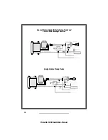
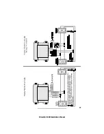
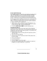
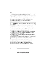
The combined type neutral safety switch requires an additional relay to
prevent the vehicle from remote starting while the key is in the ignition. Use
the attached test procedure and relay wiring diagrams. Install the complete
remote start unit and test all safety features before conducting the test
procedure.
Currently, the only vehicles with the combined neutral safety switch that
Prime is aware of are General Motors trucks, GM sport utility vehicles, GM
column shift passenger cars and Dodge Dakota pickup trucks. There may be
additional vehicles with the combined neutral safety switch that require the
additional relay.
14
PrimeStart 650 Installation Manual
Summary of Contents for PrimeStart 650
Page 1: ...PrimeStart 650 Installation Manual...
Page 2: ...PrimeStart 650 Installation Manual...
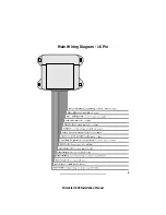
Page 5: ...3 PrimeStart 650 Installation Manual Main Wiring Diagram 16 Pin...
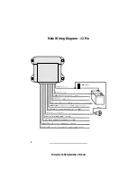
Page 6: ...Main Wiring Diagram 12 Pin 4 PrimeStart 650 Installation Manual...
Page 7: ...5 PrimeStart 650 Installation Manual Satellite Relay Module Diagram...
Page 20: ...18 PrimeStart 650 Installation Manual...
Page 21: ...19 PrimeStart 650 Installation Manual...


