background image

12

www.pridemobility.com

Jazzy 623

I V .   A S S E M B L Y

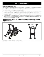
Figure 7. Universal Mounting System and Contour Seat

REAR

EXTRUSION

FRONT EXTRUSION

Seat Installation

It may be necessary to install the seat either prior to

initial operation or after transporting your power chair.

Contour seats are attached to the power base with the

Universal Mounting System (UMS). The UMS con-

sists of universal parts that may be attached to the seat,

regardless of seat width or seat depth. The two main

components are aluminum extrusions mounted to the

seat base. These extrusions attach to a pair of trapeze

bars that are mounted to the power base. 

See figure 7.

NOTE: If your power chair is equipped with a Spe-

cialty Seat, Synergy Seat, or a TRU-Balance Power

Positioning System, refer to the information provided

in separate manuals.

WARNING! Do not pick up the seat

frame by the armrests. They are free to

pivot, and you may lose control of the

seat if they do so. 

To install the seat:

1. Tilt the seat back and slide the rear extrusion onto

the rear trapeze bar. 

See figure 7.

2. Lower the front extrusion onto the front trapeze bar

until the seat locks into place.

3. Flip the seat latch safety down.

WARNING! Make sure the seat latch

safety is flipped down before using

your power chair.

4. Install the controller and route the harness to the

back of the power base. 

See figures 8 or 9.

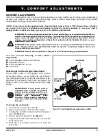
SEAT LATCH SAFETY

Figure 8. Controller Harness Routing on a Synergy Seat

TRAPEZE BARS

MANDATORY! Prevent controller

harness damage! Avoid routing the

controller harness on the outside of

the armrest pad. Route the harness

under the armrest or toward the inside

of the armrest pad. Use correct tie-

down points for controller harness to

prevent the harness from getting

caught in the drive tires, pinched in the

seat frame, or damaged when passing

through doorways. 

5. Plug the controller connector into the rear of the

power base. 

See figure 3.

6. Secure the controller harness to the armrest

receiver with wire ties. 

See figure 9.

Summary of Contents for Jazzy 623

Page 1: ...JAZZY 623...

Page 2: ...warnings and important information It is very important for you to read them and understand them completely WARNING Indicates a potentially hazardous condition situation Failure to follow designated...

Page 3: ...Since we recog nize that not all English speaking countries use the same words or spellings please refer to the following chart for some common word variations that may be encountered throughout this...

Page 4: ...e or render inoperable or unsafe any guards shields or other safety features of this product fail refuse or neglect to install any retrofit kits from time to time provided by Pride to enhance or prese...

Page 5: ...nings identified and explained in the Consumer Safety Guide that is included with your power chair Please become familiar with all the warnings and safety information found in the Consumer Safety Guid...

Page 6: ...essional specially trained in assisting a power chair user in various daily living activities As you begin using your power chair during daily activities you will probably encounter situations in whic...

Page 7: ...the armrests seatback and seat base The power base assembly includes two motor brake assemblies two drive wheels four caster wheels two batteries and wiring harnesses See figures 1 2 and 3 Figure 1 Th...

Page 8: ...e motors batteries and the battery charger is pro vided by one or more wiring harnesses See figure 3 Controller Harness Connector The controller harness connector is where the controller plugs into th...

Page 9: ...t damage to the motors and the electronics If the circuit trips allow your power chair to rest for approximately one minute Next push in the circuit breaker button turn on the controller and con tinue...

Page 10: ...anual freewheel levers for drive mode drive motor engaged See figure 5 NOTE You must turn off the power before disengaging the drive motors otherwise you may get an error code on the controller To cle...

Page 11: ...he product or making comfort adjustments NOTE Any nylon insert lock nut removed during the disassembly or adjustment of the power chair must be replaced with a new nut Nylon insert lock nuts should no...

Page 12: ...and you may lose control of the seat if they do so To install the seat 1 Tilt the seat back and slide the rear extrusion onto the rear trapeze bar See figure 7 2 Lower the front extrusion onto the fro...

Page 13: ...ll the power elevating seat l Place the seat plate interface bracket onto the actu ator See figure 10 2 Insert the supplied hardware into the actuator and tighten the hardware 3 Place the seating syst...

Page 14: ...11 and 12 Tighten the straps to sufficiently remove all slack Never attach tie downs to adjustable moving or removable parts of the power chair such as armrests front riggings and wheels Position the...

Page 15: ...S COMFORT ADJUSTMENTS After becoming familiar with your power chair s operation you may find the need to make some adjustments to increase your comfort such as seat height and angle armrest width arm...

Page 16: ...re the power chair is in drive mode 3 Unplug the controller connector s from the power base 4 Remove the seat from the power base 5 Remove both extrusions from the bottom of the seat 6 Reposition the...

Page 17: ...armrest knobs on each side of the armrest receiver bracket See figure 15 2 Loosen the knobs 3 Slide the armrests in or out to the desired width 4 Tighten the knobs Armrest Angle Adjustment To change...

Page 18: ...he controller position 1 Turn off the power to the controller 2 Unplug the controller connector s from the power base 3 Remove any wire ties securing the controller har ness to the armrest 4 Flip up t...

Page 19: ...oot platform bracket and tighten Foot Platform Depth Adjustment You can adjust the depth of the foot platform To adjust the foot platform depth 1 Remove the hardware from the foot platform bracket See...

Page 20: ...before each use of the power chair If you discover a problem contact your authorized Pride Provider for maintenance and repair Positioning Belt Your power chair may be equipped with a positioning belt...

Page 21: ...lug the charger directly into a properly wired standard electrical outlet PROHIBITED Do not allow unsupervised children to play near the power chair while the batteries are charging Pride recommends t...

Page 22: ...e batteries another full charge of at least 8 to 14 hours and operate your power chair again The batteries will now perform at over 90 of their potential 4 After four or five charging cycles the batte...

Page 23: ...per month to improve battery performance and battery life What type of batteries should I use We recommend deep cycle batteries that are sealed and maintenance free Both AGM and Gel Cell are deep cycl...

Page 24: ...ower chair for an extended period fully charge the batteries prior to storage Disconnect the battery harnesses and store the power chair in a warm dry environment Avoid temperature extremes such as fr...

Page 25: ...incontinence should be inspected often for corrosion and electronic components may need to be replaced frequently Temperature Some of the parts of your power chair are susceptible to extreme changes i...

Page 26: ...our power chair Do not overtighten any screws Check for proper tire inflation Pneumatic tires should be inflated to the psi bar kPa air pressure rating indi cated on each tire If a tire does not hold...

Page 27: ...he plastic and metal parts of your power chair Avoid using products that may scratch the surface of your power chair If necessary clean your product with an approved disinfectant Make sure the disinfe...

Page 28: ...e blocks Battery Replacement A battery wiring diagram is printed on a decal located on the front cover See the specification table for correct battery specifications MANDATORY Battery posts terminals...

Page 29: ...3 5 Remove the batteries 6 Disconnect the battery harness from each battery 7 Connect the battery harness to the new front battery according to the battery wiring diagram See figure 22 WARNING Make s...

Page 30: ...Does not power up Powers up but does not move Loose seat or seating components Corrective Maintenance If the battery condition meter does not light up when you turn on the power Check the harness conn...

Page 31: ......
Page 32: ...INFMANU4501 Product Serial Jazzy 623...

Reviews: