Pressure Tech EU-1000 Maintenance Manual Download Page 4

FILTER SYSTEM START-UP PROCEDURE 

Prior to turning on the flow to the inlet service, please make the following checks:

1. Check inside filter unit to be sure basket and filter bag (if applicable) are in housing and do not require 
    cleaning or replacement. If necessary install a clean filter basket and bag (if applicable).

2. Check that filter unit cover is securely fastened to housing. You are now ready to open the flow to the inlet 
    service line. Slowly open the inlet service line approximately 25% of normal operational flow (open slowly 
    so as not to displace filter bag inside the housing). After filter unit is pressurized and vented, slowly open 
    outlet service line unit valve until completely open. Complete opening of inlet service line until desired flow 
    rate is reached. 

Once the desired service flow has been established, the filter will operate efficiently until dirty. However, 
under no circumstances should more than 5 PSI differential pressure through the filter be obtained. 
Operating the filter unit with a high differential may cause filter bags to rupture and/or cause damage to filter 
system and downstream equipment. 

To prevent excessive drop through the filter unit, regular inspection of the filter media is required. Monitoring 
of differential pressure through the housing can be utilized as a means of determining whether or not the 
filter media needs cleaning or replacement. 

MAINTENANCE

When it becomes necessary to clean or replace filter media, follow the procedure outlined below:

1. First close the flow from the inlet service line.

2. Close the flow to the outlet service line. (In some applications closing flow to outlet is not required.)

3. Relieve the pressure from the filter unit.

OPERATION

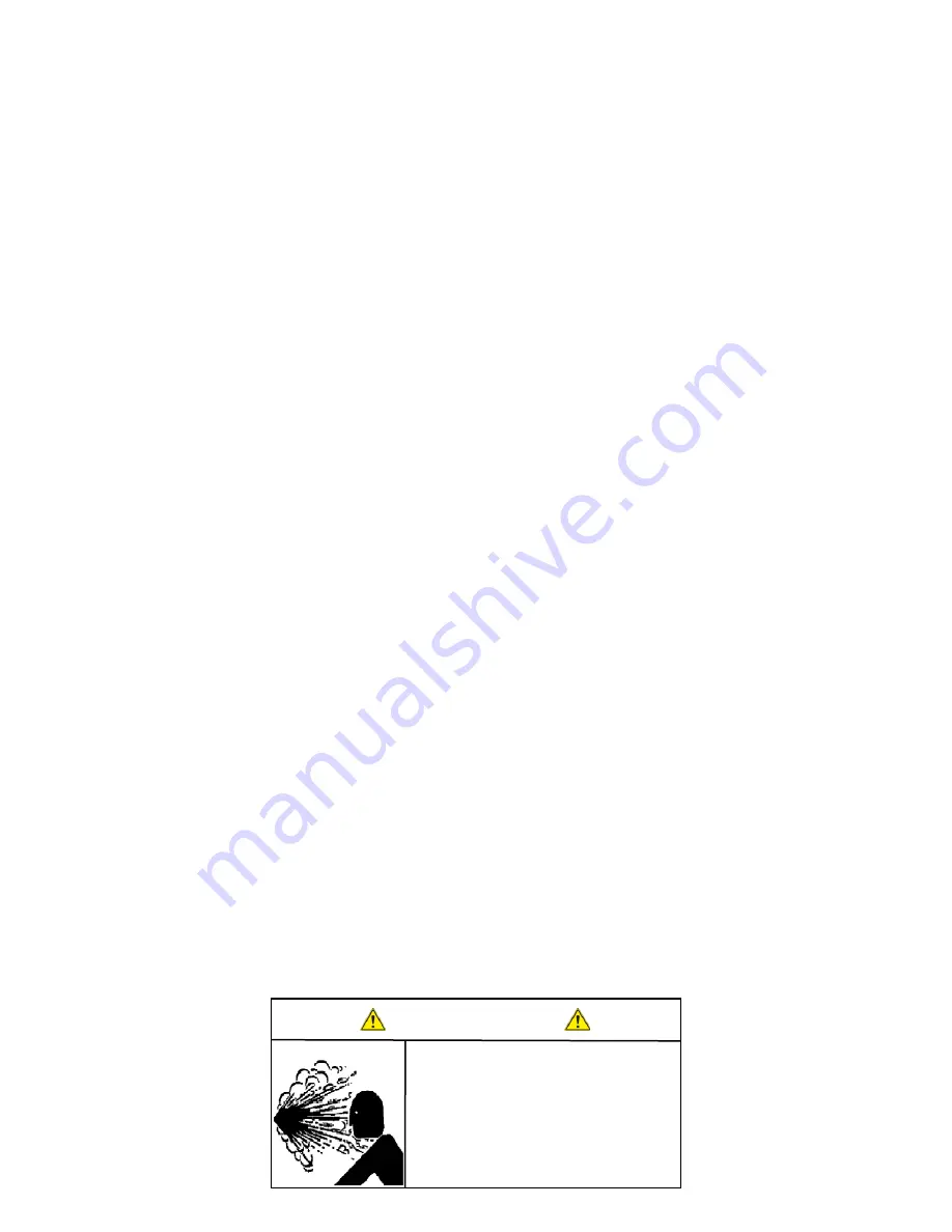
WARNING

CONTENTS UNDER PRESSURE

Relieve Pressure in accordance 

with Manufacturer’s instructions 

before opening the Filter Vessel.

FAILURE TO DO SO MAY RESULT 

IN SERIOUS BODILY INJURY.

Page 4

Maintenance Manual for EU-1000 & EU-1000-2

Summary of Contents for EU-1000

Page 1: ...Tech Turret Series High Pressure Coolant Pumps Models EU 1000 EU 1000 2 PressureTech Perfection Under Pressure New England Tool Corp 161 Sanrico Drive Manchester CT 06042 MAINTENANCE MANUAL EU 1000 2...

Page 2: ...s pg 3 Operation pg 4 Maintenance Schedule pg 6 Electrical Diagram pg 7 Sheet Metal Assembly pg 8 Motor Assembly pg 10 Valve Assembly pg 11 Left Filter Assembly pg 12 Right Filter Assembly pg 13 Maint...

Page 3: ...n high pressure pump and machine unatended Fire hazard may exist during operation of the machine and pump This is especially true if you are in the process of machining materials such as Magnesium Tit...

Page 4: ...However under no circumstances should more than 5 PSI differential pressure through the filter be obtained Operating the filter unit with a high differential may cause filter bags to rupture and or c...

Page 5: ...bag ring is firmly seated against the top of the basket flange For best results be sure filter bag is installed fully extended to the bottom of the basket 9 Inspect cover gasket for cuts or other sign...

Page 6: ...ided 1 4 clear hose this line returns to the machines oil tank This will purge air pockets in the hydraulic system WEEKLY Clean the machines main coolant tank by removing all chips and debris A dirty...

Page 7: ...PT CABLE 16 V1 990012 DESCRIPTION MAIN DISCONNECT SWITCH CONTACTOR AC 3 16 A 7 5 kW 400V 1 NO 24V DC O L RELAY MTR PROT CB COMBINATION 20 LONG SIGNAL CABLE ELECTRICAL BOX Page 7 Maintenance Manual for...

Page 8: ...T EU 1000_920001 1 EU 1000_920001 2 EU 1000 920001 3 EU 1000 940004 EU 1000 920001 5 DESCRIPTION BASE PLATE TOP BASE PLATE BLANK SIDE COVER FRONT COVER PUMP FILL COVER SHEET METAL ASSEMBLY Page 8 Main...

Page 9: ...GHT PANEL EU 1000 2_511 BOTTOM LEFT PANEL EU 1000 2_516_REAR_PANEL EU 1000 2_515_FRONT_PANEL FILTER SUPPORT EU 1000 2_517_FILLCOVER DESCRIPTION BASE PLATE TOP BASE PLATE VERTICAL SUPPORT VERTICAL SUPP...

Page 10: ...ILTER SPACER 620072 DESCRIPTION 5 HP MOTOR 1150 RPM 6 POLE 8 8 GPM DIAPHRAM PUMP BOWEX M 38 COUPLING BOWEX MOTOR GEAR BOWEX PUMP GEAR MOTOR PUMP ADAPTER 1 MALE X 75 FEMALE BRASS BUSHING 3 4 MPT X 1 2...

Page 11: ...610011 DESCRIPTION PRESSURE GAUGE MANIFOLD BLOCK PRESSURE RELIEF VALVE 1 2 NPT X 6 PIPE NIPPLE SOLENOID VALVE 24VDC SOLENOID VALVE COIL 24VDC SOLENOID ELECTRICAL CABLE 1 2 O RING MALE X 1 2 JIC MALE...

Page 12: ...4 610018 620066 610003 620004 DESCRIPTION FILTER VESSEL SHUTOFF VALVE PRESSURE GAUGE 1 4 HOSE COMPRESSION ELBOW 3 4 MNPT PLUG BRASS BALL VALVE 3 4 FNPT 3 4 MNPT X 3 4 MJIC ELBOW 3 4 NPT STREET ELBOW 3...

Page 13: ...0034 610004 610018 620066 DESCRIPTION FILTER VESSEL SHUTOFF VALVE PRESSURE GAUGE 1 4 HOSE COMPRESSION ELBOW 3 4 MNPT PLUG BLACK STEEL PIPE NIPPLE 3 4 X 2 1 2 BRASS BALL VALVE 3 4 FNPT 3 4 MNPT X 3 4 M...

Page 14: ......

Page 15: ......

Page 16: ......

Page 17: ......

Page 18: ...New England Tool Corp 161 Sanrico Drive Manchester CT 06042 tel 860 783 5555 fax 860 783 5552 email sales pressuretechsystems com www PressureTechSystems com...

Reviews: