background image

Getting Started 

2.1 

Level-Setting Procedure: AIR10, AIR12, and AIR15

AIR-Series Loudspeakers 

Owner’s Manual

3

2


Getting Started

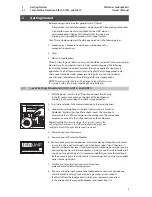
Before you begin, here are a few general rules of thumb:

•  Always make sure your loudspeakers are powered off when making connections. 
•  Do not allow your inputs to clip. Watch for the LIMIT alert on 

your loudspeaker’s display. This indicates that the inputs are 
clipping, causing digital distortion, which sounds terrible. 

Your PA and studio equipment should be powered on in the following order:

1.  Sound sources (keyboards, direct boxes, microphones, etc.) 

connected to your mixer

2.  Mixer

3.  AIR-series loudspeakers

When it’s time to power down, your system should be turned off in the reverse order. 
Now that you know what not to do, let’s get some audio going! The following 
level-setting tutorials cover best practices that can be applied to nearly every 
application. The first tutorial covers level setting for the full-range models only; 
the second tutorial describes proper level setting for a system that includes 
one AIR-series subwoofer and two full-range AIR-series loudspeakers.

NOTE:

 Please review the AIR-series Application Guide at PreSonus.com 

for complete safety information regarding flown installations.

2.1 

Level-Setting Procedure: AIR10, AIR12, and AIR15

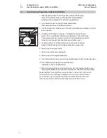
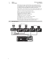
1.  With the power switch in the Off position, connect the IEC plug 

to the IEC socket connection on the back of the loudspeaker 
and plug it into a grounded AC outlet or surge protector.

2.  Turn the level knobs fully counterclockwise, to the lowest position.

3.  Connect your microphone or line-level source (such as a PreSonus 

StudioLive® digital mixer) to either or both inputs. The Line input is 
accessed via the ¼” TRS connection on the combo jack. The microphone 
preamp is accessed via the XLR connection on the combo jack. 

Power User Tip:

 If you are running a stereo system, connect the 

Left output of your mixer to the left loudspeaker’s line input, and 
the Right output to the right loudspeaker’s line input.

4.  Power on your line-level source.

5.  Power on your AIR-series loudspeaker.

6.  While speaking into a microphone or with audio playing through your line-level 

source, turn the input level knob(s) until the display shows “Limit,” then turn it 
down to just below that level. If you are using a microphone, be sure that you are 
not standing too close to the loudspeaker, as doing so could result in feedback. If 
you are not using both inputs, it is recommended that you leave the level knob 
for the unused input in the fully counter-clockwise position so as not to introduce 
noise into the signal path.

7.  Turn the master output level control until you have 

achieved a comfortable listening volume. 

8.  If you are using the input mixer of one loudspeaker to connect a microphone 

and a line-level source, or if you are running a mono system, connect 
the Mix Out from the loudspeaker to which your sources are connected 
to the line input of the second loudspeaker and repeat steps 1-8.

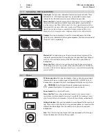
-80 -60 -40 -20 0 10

DIRECT OUT

MIX OUT


MIC

LINE

-80 -60 -40 -20 0 10

Summary of Contents for AIR SERIES

Page 1: ...AIR Series Advanced Impulse Response Loudspeakers Owner s Manual www presonus com...

Page 2: ......

Page 3: ...dure AIR15s and AIR18s 4 3 Hookup 5 3 1 Rear Panel Connections and Controls 5 3 1 1 Full Range Models AIR10 AIR12 and AIR15 5 3 1 2 Subwoofers AIR15s and AIR18s 6 3 2 Power 6 3 3 Onboard Tuning Featur...

Page 4: ......

Page 5: ...1 2 About This Manual This manual covers hardware features and functions for full range AIR series loudspeakers AIR10 AIR12 and AIR15 and for the companion AIR15s and AIR18s subwoofer We suggest that...

Page 6: ...ed installation 1 3 2 Subwoofers AIR15s and AIR18s 15 18 woofer with 3 voice coil Polarity invert Fully variable lowpass filter lets you dial in upper frequency limit Easy cardioid array presets 1 200...

Page 7: ...ker and plug it into a grounded AC outlet or surge protector 2 Turn the level knobs fully counterclockwise to the lowest position 3 Connect your microphone or line level source such as a PreSonus Stud...

Page 8: ...should be connected to Input 2 5 Connect Outputs 1 and 2 of your AIR series subwoofer to the line inputs of the left and right full range loudspeakers respectively 6 Power on your line level source 7...

Page 9: ...nput device will create a momentary spike in the audio output of your AIR series full range loudspeaker Because of this it is highly recommended that you turn down the channel trim or power down your...

Page 10: ...trol to access all the DSP functions in your AIR series loudspeaker Power User Tip A subwoofer can significantly change the frequency response of a full range system A 3 way system with a subwoofer wi...

Page 11: ...dB Default 0 dB Bass Adjusts the level of the low frequency content reproduction You can adjust the low frequency response from 10 dB to 10 dB Default 0 dB LED Turns the grille LED on Default or off o...

Page 12: ...and setting the crossover can be found in the AIR series Application Guide at PreSonus com Unit Sets the unit for the delay setting meter or foot LED Turns the grille LED on Default or off or to illu...

Page 13: ...121 dB 123 dB 124 dB Nominal Dispersion HxV 90 x 60 90 x 60 90 x 60 Inputs 2 x XLR TRS mic line combo 1 x 1 8 TRS stereo 2 x XLR TRS mic line combo 1 x 1 8 TRS stereo 2 x XLR TRS mic line combo 1 x 1...

Page 14: ...Hz to 150 Hz Maximum Output SPL 126 dB 127 dB Inputs 2 x XLR TRS line combo 2 x XLR TRS line combo Outputs 2 x XLR Link Out 1 x XLR Link Out DSP Features LCD screen with EQ and multiple presets LCD sc...

Page 15: ...Loudspeaker is on but there s no sound Check to make sure the signal is live from an external source Check that output faders are up on the mixing console and check the output level using headphones...

Page 16: ...of Coverage Provided at no additional cost Included at no additional cost Who to contact to make a claim The seller PreSonus technical support for your region What This Warranty Covers PreSonus Audio...

Page 17: ...place at our sole and absolute option products covered by this warranty at no charge for labor or materials If the product must be shipped to PreSonus for warranty service the customer must pay the in...

Page 18: ...you Exclusion of Damages PRESONUS S LIABILITY FOR ANY DEFECTIVE PRODUCT IS LIMITED TO THE REPAIR OR REPLACEMENT OF THE PRODUCT AT PRESONUS S SOLE OPTION IF PRESONUS ELECTS TO REPLACE THE PRODUCT THE...

Page 19: ...epan or large skillet heat oil on medium high and slowly add flour a tablespoon at a time to create a roux Continue cooking the roux until it begins to brown creating a dark blond roux 2 Add garlic on...

Page 20: ...Part 70 32000033 A 18011 Grand Bay Ct Baton Rouge Louisiana 70809 USA 1 225 216 7887 www presonus com AIR Series Advanced Impulse Response Loudspeakers Owner s Manual...

Reviews: