


FlacheSAN1L-D4 Quick Guide
For more information please visit our website at
www.premioinc.com
Copyright © 2016, Premio Inc. All rights reserved.
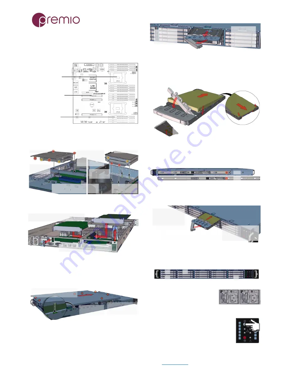
5.
Install CPU and memory
(may be sold separately)
to their respective slots on the motherboard. Please be aware
of each component’s installation requirements and
prerequisites. Refer to the motherboard’s TPS for details.
- Supports Intel Xeon E5-2600/
4600 & V3 series
- Dual Socket LGA 2011 R3
- 16 DDR4 DIMM slots
- Quad channel memory
- Supports 2133/1866/1600 LR/R/
ECC DIMM and NVDIMM
- 1.2V
- 3 PCIe Gen3 x16 slots
- PCIE6 is routed to CPU1
- PCIE7 and PCIE2 from CPU2
EP2C612D16NM
6.
Install OS disk(s)
into the bracket. There are two
locations where OS disks can be placed in replacement of:
expander and PCIe card. See below on how to install:
1. Install one or two
disk(s) to the bracket,
secure it with 4 M3
screws each at yellow
circle locations
3. Place the OS disk bracket assembly
back to the enclosure. Secure with
provided screws (red circles)
4. Connect SATA
cables and power
cables to the disk(s)
2a. Make sure
PCIE6 riser card
is removed
2b. Make sure
expander board
is removed
PCIe Location
Expander Location
7.
Install IO cards
(may be sold separately) to PCIe
slots.
A. For PCIE7 slot, remove the thumbscrews
and insert IO card to riser card
B. For PCIE6 slot, remove the bracket
and insert IO card to riser card
For more IO cards information, refer to the user’s guide for IO
cards. To install mezzanine card, remove PCIE7 riser card first.
8.
Replace the top cover.
Once we are finished with
the internals of the system, close the top of the chassis as
described below:
2. Slide the cover
forward
3. Secure the cover
with eight 6-32
thread screws
1. Place the top cover to the
chassis using the pin as a guidance
9.
Remove drive trays
from the enclosure.
1. Push the tray
latch to release
the tray handle
2. Pull the tray
handle to remove
the drive tray out
from the
enclosure bay
10.
Install drives into trays.
Follow the diagram
closely. SSD and HDD sold separately. For HDD installation,
the use of M3 screws is recommended.
1. Slide in drive with IO
connector side first to the
back of the tray
4. Snap in the
hinge back to
lock position
3. Snug the
other end of
the drive into
the tray
To remove the disk, do the steps in reverse.
Poke from the bottom hole to help lift the disk.
2. Make
sure the
drive goes
underneath
the hooks
11.
Place the unit to the rack.
Two types of slide
rail (22” and 28” long) are available. Secure with screw as
indicated. Please refer to Rail Kit Installation Guide on how to
mount the enclosure to the rack.
22"
28"
12.
Install the populated drive trays
into the
enclosure with the drives properly secured to the hard drive
trays.
1. Push the tray by the
latch all the way into the
drive bay to ensure a
complete insertion
2. Secure the drive tray to
the enclosure by placing the
tray handle to lock position
13.
Drive mapping
begins from top to bottom and to
the right, depending on the cable connection of the expander
/ on-board SATA ports.
1
20
4
5
14.
Plug in the power
cords
to the AC receptacles on the
back of the unit and secure it with
the wire lock.
15.
Press the power button
on the
front of the unit after connecting a monitor
and input devices, and get ready for software
setup.