

FlacheSAN2-D4 Hardware Quick Guide
For more information please visit our website at
www.premioinc.com
Copyright © 2015, Premio Inc. All rights reserved.
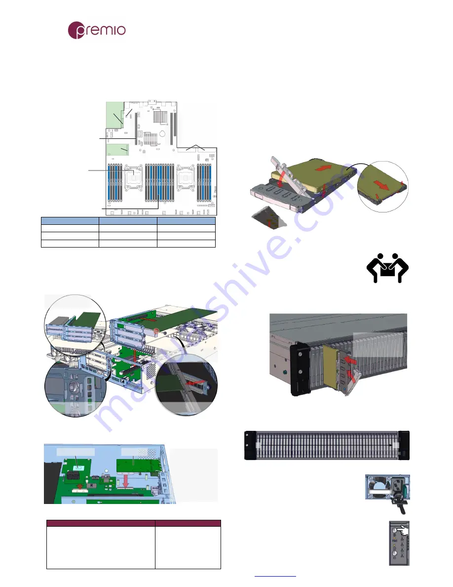
1. Push the tray by the
latch all the way into the
drive bay to ensure a
complete insertion
2. Secure the drive tray
installation by placing the
tray handle to the lock
position
6.
Install CPUs, memory
(not included) and heat sinks
to their respective slots. Please be aware of each
component’s installation requirements. For details, refer to
S2600WT motherboard TPS. Replace the air duct once
finished.
Two LGA2011-3 (Socket R3)
One or two Intel Xeon E5-
2600 v3 processors
TDP up to 145W
24 DIMMs, 3/channel, 4ch/
CPU
RDIMM, LRDIMM DDR4
1600, 1866 (RDIMM only),
2133 MT/s
Start populate on blue slot
first farthest from CPU
Ri
ser
Sl
o
t
1
Ri
ser
Sl
o
t
2
Ri
ser
Sl
o
t
3
CPU1
CPU2
RAID
Module
IOM
PSU Connectors
Riser Card 1 and 2 are Gen3
x24 divided into 3 PCIe slots
each
All PCIe slots are Gen3 x8,
except Riser 3 Top PCIe slot
(Gen2 x4)
See table below for CPU
association
C612
RMM4
Riser Slot 1
Riser Slot 2
Riser Slot 3
Top Slot: CPU 1
Top Slot: CPU 2
Top Slot: CPU 2
Middle Slot: CPU 1
Middle Slot: CPU 2
Bottom Slot: CPU2
Bottom Slot: CPU2
Bottom Slot: CPU2
7.
Install IO cards
(optional) into PCI-e riser cards.
The unit has two PCIe riser card assemblies. The left assembly
holds five PCIe IO cards for CPU2, the right assembly is for
three PCIe IO cards for CPU1. See below for installation:
2. Remove the IO card dummy cover and insert IO card
to PCIe slot on the riser, secure with screw (red circle)
1. Remove the tool-less
riser card assembly
3. Loosen the thumbscrew and
open the card guide bracket
5. Close the card guide bracket
and secure the thumbscrew
4. Replace riser card assembly to motherboard
PCIe slot. Insert the hooks to their slots
To install IO Module and RAID mezzanine card, removing the
PCIe riser card is recommended. See below for the location.
IO Module
RAID Mezzanine
1. Remove the cut off
from the rear panel if
necessary
2. Insert the module to
the connector
3. Secure it with stand
off and screws
Below is the list of compatible IOM and ROC modules:
IO Module compatible cards
ROC Module comp. cards
Dual SFP+ port 10GbE (AXX10GBNIAIOM)
Single port QSFP FDR 56GT/S IB (AXX1FDRIBIOM)
Dual port QSFP FDR 56GT/S IB (AXX2FDRIBIOM)
Single port QSFP+ 40GbE (AXX1P40FRTIOM)
Dual port QSFP+ 40GbE (AXX2P40FRTIOM)
Quad port RJ45 1GbE i350 (AXX4P1GBPWLIOM)
Dual port RJ45 10GbE X540, Single port X520
RMS25CB040, RMS25CB080
RMS25JB040, RMS25JB080
RMS25KB040, RMS25KB080
RMS25PB040, RMS25PB080
RMS3CC040, RMS3CC080
RMS3HC080, RMS3JC080
RMT3CB080, RMT3PB080
8.
Put the top cover.
Once we are finished with the
internals of the system, close the top of the chassis.
9.
Remove drive trays
from the enclosure (if no SSDs
are installed already).
10.
Install drives into trays.
Follow the diagram
closely. SSDs can be provided and installed by request.
1. Slide the drive in with the
IO connector side head first
to the back of the tray
4. Snap in the
hinge back to
lock position
3. Snug the
other end of
the drive into
the tray
2. Make
sure that
the drive
goes
underneath
the hooks
To remove the disk, do the steps in reverse.
Poke from the bottom hole to help release the disk.
11.
Place the unit to the rack.
Refer to Rail Kit
Installation Guide on how to mount the
enclosure.
Caution:
At least two people are required to
lift a fully populated chassis
12.
Install the populated drive trays
into the
enclosure with the drives properly secured to the hard drive
trays.
13.
Drive mapping
incrementally goes from left to right
depending on the connection to the IO cards.
48
1
14.
Plug in the power cords
to the
AC receptacles on the back of the unit and
secure it with the cable tie.
15.
Press the power button
on the front
of the unit after connecting a monitor and input
devices, and get ready for software installation.