background image

www.mounts.com  |  North America  800.368.9700  | Interna1-714-632-7100

Installation Guide

LMVSP

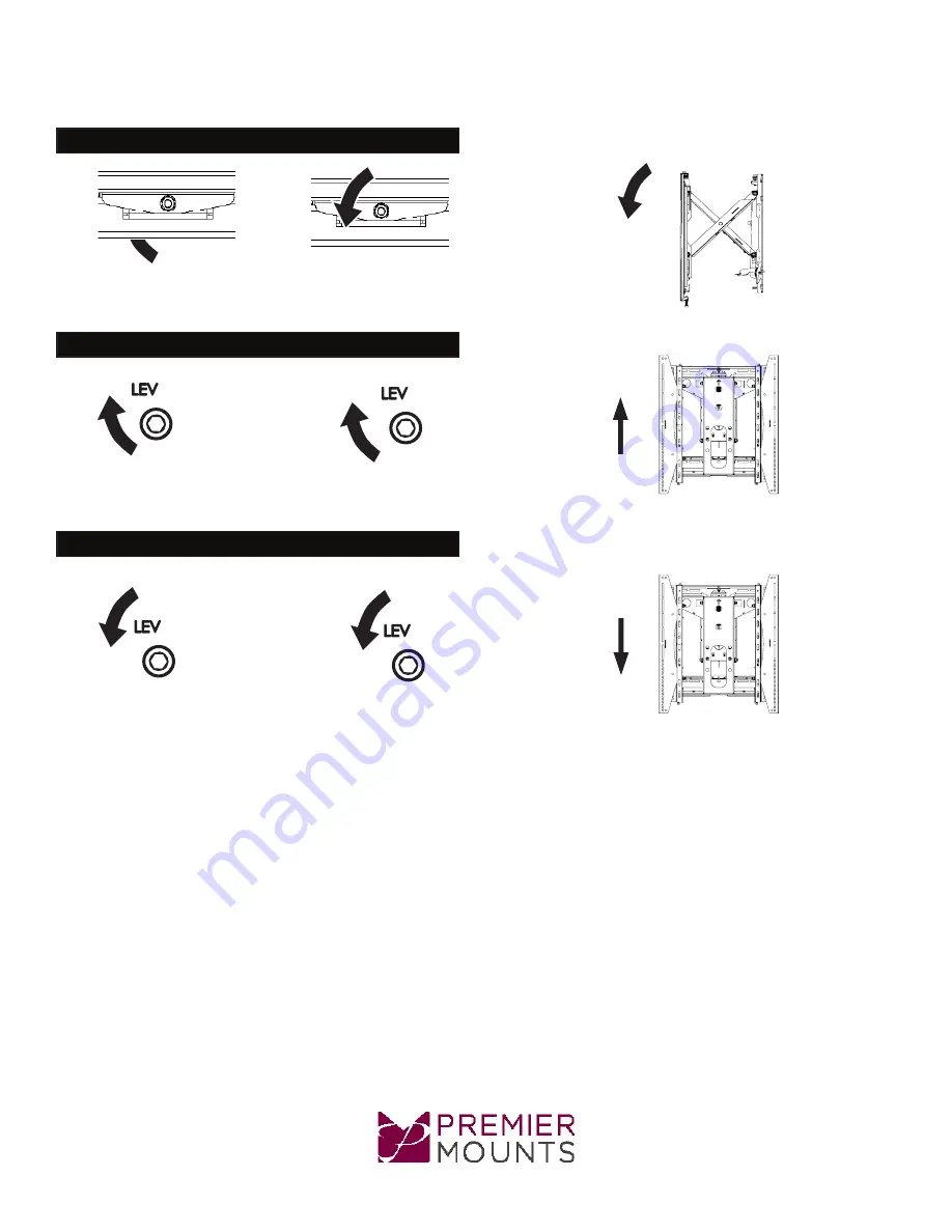
Positive / Negative Tilt

Negative Tilt 

control

Positive Tilt 

Control

Post Leveling (Up)

Left Control

Right Control

Post Leveling (Down)

Left Control

Right Control

Page 12

Summary of Contents for LMVSP

Page 1: ...www mounts com North America 800 368 9700 International 1 714 632 7100 2620 Palisades Drive Corona CA 92882 Installation Guide LMVSP Release Pop Out Ultra Slim Portrait Mount...

Page 2: ...rs Qty 4 M8 Nylon Nut Qty 4 5 16 Flat Washers Qty 4 Universal Washers Qty 4 Pencil Protective Eyewear Electronic Stud Finder M6 or 1 4 Drill Bit 3 8 Masonry Drill Bit Portable Drill Phillips Head Scre...

Page 3: ...rk each of the wall studs Use a pencil to mark the upper right mounting location of the wall stud Drill a pilot hole using a M6 or 1 4 drill bit on the stud that was marked on the upper right 1 Place...

Page 4: ...pencil to mark the remaining three 3 mounting locations Drill a pilot hole in each of the three 3 marks with a power drill and a M6 or 1 4 drill bit 1 Insert one 1 5 16 x 3 lag bolt and one 1 5 16 wa...

Page 5: ...to level the mount and another person to mark the mounting locations Drill a pilot hole in each of the four 4 mark areas with a 3 8 masonry drill bit Insert the Finned Anchors into each hole Lightly...

Page 6: ...o the wall during installation depending on the wall material You may utilize the same spacer for multiple LMVSP installations Start Multiple LMVSP mounts can be installed using model specific spacers...

Page 7: ...eter screw for the threaded insert If the screw you selected is longer than the 1 8 allowance mark on the small straw or toothpick as shown in Figure 2 and Figure 3 do not use this screw The screw len...

Page 8: ...mounting screw and the mounting bracket as shown Premier Mounts Universal Spacers allow you to attach the mounting bracket to flat panels which have recessed or uneven mount points Each Universal Spac...

Page 9: ...ou are certain that top and bottom hooks of both mounting brackets are securely seated on the upper and lower mounting rails of the wall panel 1 Raise the flat panel past the top and bottom mounting r...

Page 10: ...cking Safety Screw 1 per Bracket Locking Safety Screw Installation Post Installation Adjustments The LMVSP has a set of post installation adjustments on each mounting bracket Figure 1 Use the M5 Allen...

Page 11: ...800 368 9700 International 1 714 632 7100 Installation Guide LMVSP Move Inward Left Control Right Control Move Outward Left Control Right Control Tilt Left Left Control Right Control Tilt Right Left C...

Page 12: ...00 368 9700 International 1 714 632 7100 Installation Guide LMVSP Positive Negative Tilt Negative Tilt control Positive Tilt Control Post Leveling Up Left Control Right Control Post Leveling Down Left...

Page 13: ...appens when weight is transferred to the ultra thin bezels of video wall installations if the recommended gap specifications of 050 is not maintained vertically and horizontally This results in image...

Page 14: ...ull the front of the LMVSP to extend the scissor arms Figure 2 2 Loosen the locking safety screws on both mounting brackets 3 Tilt up the bottom of the flat panel then set their kickstands against the...

Page 15: ...mproper installation modification use or misuse of its products NOTWITHSTANDING ANYTHING TO THE CONTRARY IN THIS WARRANTY THIS WARRANTY IS LIMITED TO FIVE YEARS FROM THE DATE OF PURCHASE IN THE EVENT...

Reviews: