Predator 69671 Owner'S Manual & Safety Instructions Download Page 21

      Page 21

For Generator technical questions, please call 1-800-444-3353.

For Engine technical questions, please call 1-800-520-0882.

Item 69671 / 69677        

SAFETY

OPERA

TION

MAINTENANCE

SETUP

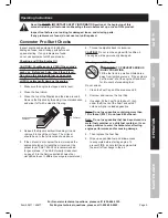
Record Product's Serial Number Here: 
Note: If product has no serial number, record month and year of purchase instead.
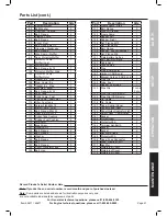
Note:

 Some parts are listed and shown for illustration purposes only, and 

are not available individually as replacement parts.

Part

Description

Qty

87

Contactor Assy.

1

88

Bolt Washer

2

89

Coil Assy., Charge

1

90

Bolt, Flange

2

91

Clamper, Cord

1

92

Bolt, Flange

1

93

Cover, Dust

1

94

Bolt, Flange M5×10

3

95

Grommet, Crankcase

1

96

Bolt, Flange

4

97

Stay Comp., Muffler

1

98

Seal, Protector Muffler

1

99

Protector Comp., 

Muffler Inner

1

100 Muffler Assy.

1

101 Bolt, Flange, 6×14

7

102 Protector, Muffler Side

1

103 Protector Comp., 

Muffler Outer

1

104 Gasket, Ex., Pipe

1

105 Pipe, Comp., Ex.

1

106 Gasket, Ex., Pipe

1

107 Nut, Hex., 8Mm

2

108 Bolt, Flange, 8×32

2

109 Fuel  Tank  

1

110 Cock Comp., Fuel

1

111 Cap Comp., Fuel Filler

1

112 Filter, Fuel Tank

1

113 Screw, Flat, M5×12

2

114 Meter Comp., Fuel

1

115 Bolt, Flange, M6×25

4

116 Washer φ6×Φ25×2

4

117 Collar, Tank Cushion

4

118 Rubber, Fuel Cushion

4

119 Alternator

1

120 Brush Assy.

1

121 Housing, Rr

1

122 Bolt, Flange

4

123 Bolt, Flange

2

124 Washer

1

125 Bolt, Flange

7

126 Avr

1

127 Bolt, Flange,

3

128 Cover, Generator End

1

129 Bolt, Hex.

1

Part

Description

Qty

130 Frame Comp., Side

1

131 Bolt, Flange

2

132 Stay, Air Cleaner

1

133 Frame Comp.

1

134 Rubber, Left

2

135 Rubber ,Right

2

136 Nut, Flange, M10

4

137 Nut, Flange, M8

4

138 Bolt, Flange

4

139 Rubber , Shock Absorber

4

140 Nut, Flange, M6

4

141 Plate,Battery Setting

1

142 Bolt, Battery Setting

2

143 Cable Assy.

1

144 Ground Line

1

145 Pipe

1

146 Pipe (CARB only)

1

147 Carbon (CARB only)

1

148 Bracket,Carbon (CARB only)

1

149 Pipe Clip

2

150 Tube, Fuel

1

151 Rubber, Fuel Tube

1

152 Pipe Clip

CARB

EPA

153 Pipe Clip (CARB only)

1

154 Pipe Clip (CARB only)

2

155 Tie, Cable

2

156 Tie, Cable

2

157 Case, Control Panel

1

158 Control Panel Assy. 

1

159 Panel Output Indicator Light

1

160 Switch Assy., Combination

1

161 Socket

1

162 Protector 8A

1

163 Protector 28A

2

164 Terminal Set,Earth

1

165 Socket

2

166 Socket

2

167 Rectifier Bridge

1

168 Protector 20A

2

169 Case, Fuse Connector

2

170 Fuse , Rectifier (5A)

2

171 Rectifier

1

172 Waterproof Cover

2

173 Waterproof Cover

2

174 Waterproof Cover

5

Parts List (cont.)

Summary of Contents for 69671

Page 1: ......

Page 2: ...wed including the following Set up Precautions 1 Gasoline fuel and fumes are flammable and potentially explosive Use proper fuel storage and handling procedures Do not store fuel or other flammable ma...

Page 3: ...from the equipment especially while it is operating 6 Keep all spectators at least six feet from the Engine during operation 7 Fire Hazard Do not fill gas tank while engine is running Do not operate i...

Page 4: ...28 Keep grounded conductive objects such as tools away from exposed live electrical parts and connections to avoid sparking or arcing These events could ignite fumes or vapors 29 Stay alert watch what...

Page 5: ...speed 6 Wear ANSI approved safety goggles heavy duty work gloves and dust mask respirator during service 7 Maintain labels and nameplates on the equipment These carry important information If unreadab...

Page 6: ...allons 23L Engine Oil Type SAE 10W 30 above 32 F 5W 30 at 32 F or below Capacity 1 16 Quart 1 1L Run Time 50 load 12 hr Operational Volume 76 dB Available accessories Wheel kit sold separately Item 69...

Page 7: ...Connect tools and equipment only to the Receptacle 120 volt or 240 volt that is compatible with the electrical characteristics and rated capacities of the tools and equipment being used 3 ON OFF Circ...

Page 8: ...electronic equipment includes but is not limited to audio video equipment some television sets computers and printers Sensitive electronic equipment should be operated on approved inverter type gener...

Page 9: ...threading it in and remove it to check the oil level The oil level should be up to the full level as shown above 5 If the oil level is at or below the low mark add the appropriate type of oil until t...

Page 10: ...trical load 3 Plug in products 4 When finished using the Generator disconnect all electrical loads Note Do not allow generator to run out of fuel with loads attached 5 Turn off the Engine 6 Allow the...

Page 11: ...ow the engine to run at no load for five minutes with no load after each start up so that the engine can stabilize For MANUAL START A Turn the Engine Switch to ON B Grip the Starter Handle of the Engi...

Page 12: ...first b Connect inductive load appliances tools and equipment next Inductive loads are small hand tools and some small appliances c Connect any lights next d Voltage sensitive appliances tools and eq...

Page 13: ...ct watts needed To Calculate Wattage Volts and amps can be multiplied together to get watts volts x amps watts To Calculate Additional Start Up Watts If They Are Not Listed For equipment with a motor...

Page 14: ...ping the Engine in an Emergency 1 To stop the engine in an emergency turn the Engine Switch off NOTICE Generator shut off under load may damage the generator and attached equipment Stopping the Engine...

Page 15: ...ity to safely service the equipment or engine have a qualified technician service the equipment instead Cleaning Maintenance and Lubrication Note This maintenance schedule is intended solely as a gene...

Page 16: ...e engine is stopped and is level 2 Close the Fuel Valve 3 Place a drain pan not included underneath the crankcase s drain plug 4 Remove the drain plug and if possible tilt the crankcase slightly to he...

Page 17: ...ally enter the engine and cause rust damage Apply a thin coat of rust preventive oil to all metal parts 2 FUEL WARNING TO PREVENT SERIOUS INJURY FROM FIRE Drain the fuel tank in a well ventilated area...

Page 18: ...oke to RUN position Remove spark plug and pull the start handle several times to air out the chamber Reinstall spark plug and set Choke to CHOKE position 9 Replace Fuel Filter IGNITION SPARK RELATED 1...

Page 19: ...ine to warm up prior to operating equipment Engine knocks 1 Old or low quality gasoline 2 Engine overloaded 3 Incorrect spark timing deposit buildup worn engine or other mechanical problems 1 Fill fue...

Page 20: ...tor Carburetor 1 55 Packing Insulator 1 56 Carburetor Assy 1 57 Packing Air Cleaner 1 58 Nut Flange 2 59 Air Cleaner Assy 1 60 Element Air Cleaner Assy 1 61 Clip Harness 1 62 Grommet Cord 1 63 Holder...

Page 21: ...e M6 25 4 116 Washer 6 25 2 4 117 Collar Tank Cushion 4 118 Rubber Fuel Cushion 4 119 Alternator 1 120 Brush Assy 1 121 Housing Rr 1 122 Bolt Flange 4 123 Bolt Flange 2 124 Washer 1 125 Bolt Flange 7...

Page 22: ...uestions please call 1 800 444 3353 For Engine technical questions please call 1 800 520 0882 Item 69671 69677 SAFETY OPERATION MAINTENANCE SETUP Assembly Diagram Note Parts 146 148 and 153 154 are on...

Page 23: ...em on your engine for the periods of time described below provided there has been no abuse neglect or improper maintenance of your engine Your emission control system may include parts such as the car...

Page 24: ...arts which are not authorized by HFT b Improper installation adjustment or repair of the engine or of any warranted part unless performed by an authorized warranty center c Failure to follow recommend...

Reviews: