background image

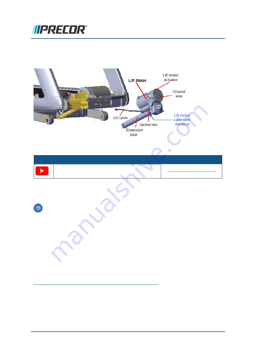
Lift Motor Replacement

This procedure provides instruction to remove and replace the Lift Motor.

Videos

Service Video

Link

TRM400 Lift Motor Replacement

LIft Motor Replacement

Procedure

Review entire procedure before starting.

Note

: The replacement lift motor must be calibrated prior to installation.

1. If not already set to 0% incline, set the incline to 0%.

2. Switch the treadmill power “OFF” and

unplug

1

the power cord.

3. Disconnect the lift motor cable connectors from

LPCA

2

J1 and J7 connectors.

4. Remove the lift motor’s green frame ground wire from the frame.

1

Disconnect a device power cord plug or cable connector from the power receptacle or out-

let.

2

Lower Printed Circuit Assembly board; also refered to as the Lower PCA or simply as the

lower board. On treadmills, it is the console to base function interface and the motor con-
troller unit (MCU). On self-powered units, it is the lower PCA console to base function inter-
face.

Contact Precor Customer Support at [email protected] or 800.786.8404 with
any questions.

Page 80

6 Replacement Procedures

Lift Motor Replacement

Summary of Contents for TRM 425

Page 1: ...Service Manual Precision Series 400 line TRM400 14 Treadmills ...

Page 2: ...Number Label Location 8 Orientation 8 Tools and Supplies 9 Specification Summary 10 Fastener Torque Specification 10 Calibration Specification 11 Belt Tension Specification 11 Bolt Grade Identification 11 Bolt Grade Markings Chart 12 Parts 12 Lubricants 13 Cleaning Procedure 13 Approved Cleaning Products 13 Cleaning Procedure 14 Power Requirements 14 Equipment Power Requirements 14 Contact Precor ...

Page 3: ...Standard Service menus 28 Standard Service Menus 29 R40 Standard Service Menus 29 Hardware Validation 51765761 29 Information Display 65 30 My Settings Menu 5671 31 R20 Standard Service Menus 31 Hardware Validation 51765761 31 Information Display 65 32 My Settings Menu 5671 33 DEMO Mode R40 34 Enter DEMO mode 34 Disable DEMO mode 35 Standard Service Menus 36 About 36 Service Menu Access Codes 36 H...

Page 4: ...8 Running Belt Tension and Tracking Adjustment 52 About 52 Videos 52 Tools 52 Specification 52 Procedure 52 Running belt alignment and tracking adjustment 55 Lift Motor Calibration 58 About 58 Specifications 58 Videos 58 Lift Motor Calibration 58 Replacement Procedures 62 Available Replacement Procedures 62 Drive Belt Replacement 63 About 63 Procedure 63 Drive Motor Replacement 65 Contact Precor C...

Page 5: ...ocedure 77 About 77 Procedure 77 Lift Motor Replacement 80 Videos 80 Procedure 80 Lift Platform Replacement 83 Procedure 83 Lower PCA LPCA Replacement 86 Procedure 87 Troubleshooting 92 About 92 Introduction to Troubleshooting 92 Basic Troubleshooting Steps 92 Validate the customer reported issue 93 Verify Input Power 93 Verify reproduce the customer issue 94 Contact Precor Customer Support at sup...

Page 6: ...leshooting Guide 98 Troubleshooting with Error Codes 99 Getting Starting 99 Troubleshooting with Error Codes 99 Viewing Error Codes 99 Quick Reference 99 System Troubleshooting Procedures 102 AC Input Power Troubleshooting 103 Heart Rate Monitor Troubleshooting 105 LIft System Troubleshooting 106 LPCA Fan Troubleshooting 110 Speed Sensor Troubleshooting 112 Running Belt Troubleshooting 114 Prevent...

Page 7: ... 124 Exploded View Diagrams and Parts List 127 Exploded View Diagram 128 Parts List 134 Appendix A Edition Information i Edition i Additional Documentation i Copyright i Appendix B Notices and Safety ii Trademarks ii Intellectual Property ii Warranty ii Safety Notices iii Service Safety Guidelines iii Contact Precor Customer Support at support precor com or 800 786 8404 with any questions Page vii...

Page 8: ...120 VAC1 and 240 VAC models Model Configuration TRM425 TRM400 14 base with R20 console speed 0 5 12 mph 0 8 19 2 kph incline 2 Decline 15 Incline TRM445 TRM445 14 base with R40 console speed 0 5 12 mph 0 8 19 2 kph incline 2 Decline 15 Incline Service manual contents The service manual contains information to service repair troubleshoot and maintain the machine base This manual does not include co...

Page 9: ...ature Videos topic l Product Literature Videos on page 122 See Also Product Literature Videos on page 122 General Information on page 5 Operation Verification on page 17 Standard Service Menus on page 36 Adjustment Procedures on page 47 Replacement Procedures on page 62 Troubleshooting on page 92 Preventive Maintenance PM on page 117 System Wiring Diagram on page 121 Parts on page 124 Service Safe...

Page 10: ... accessory attachments that are not recommended by the manufacturer Non OEM accessories can cause injuries l Do not stand or climb on the handlebars display enclosure or cover l On a self powered unit it will either be necessary to either equip the unit with the optional external power supply or have an assistant pedal on the unit while voltage measurements are being taken Because of the danger of...

Page 11: ... l During service operations you will be very close to moving machinery and voltage bearing components o Remove jewelry especially from ears and neck o Tie up long hair o Remove neck ties o Do not wear loose clothing See Also Notices and Safety on page ii Safety Notices on page iii Contact Precor Customer Support at support precor com or 800 786 8404 with any questions Page 4 1 Introduction Servic...

Page 12: ...uty motor The motor controller MC2 implements Integrated Foot Plant Technology and Pulse Width Modulated PWM drive tech nology for high reliability and accurate speed control Emergency Stop ESTOP3 Exersicer safety clip and lanyard connected to the stop switch to immediately switch off power bringing the treadmill to a stop Heart Rate Two Heart Rate sensor types l Touch Handheld Handlebar Heart Rat...

Page 13: ...igit alphanumeric code AAAXXX containing the product type product line console type and feature level designator l AAA three alpha character PRODUCT TYPE designator l X 1 digit numeric PRODUCT LINE designator l X one digit numeric CONSOLE type designator l X one digit numeric FEATURE LEVEL designator Example Product model number TRM2833 l TRM Treadmill l 8 Experience Line 1Ground Effects Impact Co...

Page 14: ...eatures UBK Standard features SBK5 Standard features 3 TRM Fixed Ramp AMT Fixed Step Height EFX Moving Ramp Fixed Arms 2 EFX Man Ramp Mov Arms 1 EFX Fixed Ramp Moving Arms Serial Numbers About The serial number uniquely identifies each machine The serial number is an alphanumeric code comprised of a four character model designator a 1 letter build month code a 2 digit day built a 2 digit year buil...

Page 15: ...el to verify the machine serial num ber Do not use a label attached to a plastic cover the cover may have been replaced from a different machine Orientation The equipment orientation front right left back is referenced to an exerciser standing on the machine facing the console Contact Precor Customer Support at support precor com or 800 786 8404 with any questions Page 8 2 General Information Orie...

Page 16: ...es 9 in lbs to 100 in lbs 83 ft lbs AC2 Clamp on averting current meter DVM Multimeter 1Torque is a measure of the force that can cause an object to rotate about an axis Bolt nut example 5 NM torque is equivalent to 5 newton s of force applied one meter from the center of the bolt 6 ft lb is equivalent to 6 lbs of force applied 1 foot away from the center of the bolt 2Alternating Current electric ...

Page 17: ...valent synthetic teflon based grease Mobil 1 NLGI 2 Teflon Synthetic Grease Specification Summary Fastener Torque Specification System component fastener torque specification System Component Specification RF2 coax connector 2 4 in lbs 0 271 Nm Display mounting fasteners 180 in lbs 20 Nm Set screws 300 in lbs 34 Nm Plastite screw fasteners 20 in lbs 2 3 Nm Flathead screws 25 in lbs 2 8 Nm 1Heart R...

Page 18: ...dial reading per cent 3 55 0 55 1 1 Referenced to belt gauge set to 3 0 0 0 with no belt tension Bolt Grade Identification Bolt grade markings are used to categorize bolts according to the bolt material man ufacturing process and mechanical properties The grade of the bolt is stamped on the head of the bolt US SAE bolts The bolt grade markings are determined by the number of the lines stamped on t...

Page 19: ...or If you use parts not approved by Precor you could void the Precor Limited War ranty Use of parts not approved by Precor may cause injury There is a copy of the parts Exploded View Diagram and Parts Identification List included in the Parts chapter see Parts that you can use as a quick reference It is recommended that you go to the servicer partners Precor Connect or Precor Connection website to...

Page 20: ... not apply any lubricants or wax to the deck and belt Do not use Wax Blast silicon sprays or other applied lubricants The use of these lubricants will quickly degrade the low friction surface of the deck Cleaning Procedure Only use the following approved cleaning products and procedures to safely clean and pre vent damage to the machine surfaces Approved Cleaning Products Approved equipment and co...

Page 21: ...spray directly onto the equipment surfaces 2 Rinse surfaces using a clean lint free cloth dampened with water only 3 Then completely dry with another clean lint free cloth Power Requirements Equipment Power Requirements The equipment input power from the wall outlet receptacle must be a good quality and stable power signal not fluctuating or intermittent to insure the best performance and trouble ...

Page 22: ...h cir cuit outlet That means that no other devices can be connected to the same circuit outlet receptacle l Individual branch circuit An individual branch circuit provides a hot conductor and neutral conductor to a receptacle The conductors must not be looped daisy chained or connected to any other conductors or receptacles The circuit must be grounded according to NEC guidelines or local region e...

Page 23: ...Contact Precor Customer Support at support precor com or 800 786 8404 with any questions Page 16 2 General Information Equipment Spacing Requirement ...

Page 24: ...e of the error 2 Resolve any current active logged error code issues 3 Press HOME to exit the Error Log 4 Clear error codes and Reset the Error Log l Access the Hardware Validation 51765761 service menu see Standard Service Menus on page 36 l Use the down arrow softkey to scroll down and select the Error Log Reset softkey l Select Test Start The screen will transition to the System Settings menu T...

Page 25: ...rdware Validation Diagnostic Test menu press the Home softkey Machine Operation Test This test verifies the console functionality motion controls metric indicators and machine operation SPEED control test 1 Do this test while walking on the machine and the INCLINE set to 0 incline 2 Select QUICKSTART to begin a manual workout 3 Operate the SPEED motion control from minimum to maximum range while v...

Page 26: ...ears or frayed edges Also check the seam for damage INSPECTING THE RUNNING BELT CONDITION Verify the running belt alignment and tracking 1 Step off the running belt and operate the treadmill at 12 mph 19 kph for one minute 2 Verify the running belt alignment and tracking remains centered RUNNING BELT ALIGNMENT AND TRACKING PROCEDURE ESTOP1 Switch Test Verify the ESTOP emergency stop switch operati...

Page 27: ...verify the equipment operation Error Code Verification Test Verify that there are no current active logged error codes 1 Access the Error Log and record any current active logged error codes l From the Home screen press and hold the PAUSE key for 5 6 seconds o If there are no errors the STUCK KEY message will scroll across the display o If there are any logged errors the error code will be display...

Page 28: ...it when all keys have been pressed Pressing down Workouts for 5 seconds also exits the test l LCD Test o Test will light up all segments and sections of the display l Heart Rate Test o Heart rate is acquired and displayed l Machine Tests Press Go to access the machine tests o Belt Speed Test Range 0 5 mph to 12 0 mph in 0 1 increments in 0 1 increments n Press Go to start the Belt Speed Test IMPOR...

Page 29: ...s to the minimum speed level l Make sure that the running belt speed change is smooth and that there are no unusual noises l Verify that the console SPEED indicators and workout metric displays are showing correct information INCLINE control test 4 Set the SPEED between 2 3 mph and walk on the belt while performing this test 5 Operate the INCLINE motion controls from minimum to maximum range while...

Page 30: ... stop 3 Inspect the condition of the ESTOP lanyard clip that the spring is in place and that the clip will firmly hold when attached to the runner 4 Make sure that the clip is properly stowed and not wrapped around the handle bars Heart Rate Monitor Test Verify the Handheld Handlebar Heart Rate HHHR1 function 1 Access the Hardware Validation Test 51765761 and do the Heart Rate Test Return to servi...

Page 31: ...Contact Precor Customer Support at support precor com or 800 786 8404 with any questions Page 24 3 Operation Verification R20 Operation Verification Test ...

Page 32: ...ine operation 65 Information Display 1 Information page provides product software hardware version and equipment usage information 2 Display Error Log provides his tory of event error codes and dia gnostics used for maintenance and troubleshooting 5671 My Settings Customizable user workout set tings 5555 DEMO mode DEMO mode is used to demon strate the R40 console Workout pro gram screens DEMO mode...

Page 33: ...Validation Diagnostics Set of automated diagnostic tests used to troubleshoot calibrate and verify machine operation 65 Information Display Provides equipment usage inform ation hardware software pn ver sion information and Error Log access 5671 My Settings Allows you to customize the equip ment user interface localization and Workouts default settings Access code 536 can be used to access the Har...

Page 34: ...names In this case the top and bottom softkeys remain active Simultaneously select and release the right side top and bot tom blank softkeys to continue 3 Use the numbered softkeys to type in the Service Menu Access Code see on page 25 and select Next to access the Service menu Contact Precor Customer Support at support precor com or 800 786 8404 with any questions Page 27 4 Standard Service Menus...

Page 35: ...ect Release the Reset Pause key 2 Type in the service access code using the USER keys Note Use the Left Right arrow keys to scroll 3 Press GO to enter the access code Contact Precor Customer Support at support precor com or 800 786 8404 with any questions Page 28 4 Standard Service Menus How to Access the Standard Service Menus ...

Page 36: ...console configuration How to run a test Select Test to start the test follow prompts to execute the test and select Stop Test to exit Hardware Validation diagnostic tests DIAGNOSTIC TEST TEST DESCRIPTION Display GUI Metric Test Test console LED lights and backlight o Backlight brightness changes o Numerals cycle properly KEY Test Test hard keys Heart Rate Test Heart rate is acquired and displayed ...

Page 37: ... total machine usage hours hours min This value is stored in the upper PCA in the console so if that PCA is replaced the hours of use would start again from 0 SW Release P N The operating system software part number Hardware Version Hardware version Console S N Console serial number LPCA2 VersionSW The LPCA software version uPA BOOT SW The console upper boot software version information 1Printed c...

Page 38: ...Menus R20 Standard Service Menus The Standard Service Menus include the Hardware Validation Information and My Set tings service menus TIP To learn additional information about the R20 console standard service menus refer to the TRM425 Owners Manual see Owners Manual Hardware Validation 51765761 Service Access Code 51765761 see R20 How To Access Standard Service menus on page 28 The Hardware Valid...

Page 39: ...Nominal value 13 5 2 incline l Nominal value 37 5 0 incline l Nominal value 242 5 15 incline Information Display 65 Service Access Code 65 see R20 How To Access Standard Service menus on page 28 The Information Display provides the equipment usage information software pn version information and Error Log access INFORMATION DISPLAY DESCRIPTION ODOMETER The total number of accumulated miles or kilom...

Page 40: ...n about the R20 console My Settings service menu refer to the TRM425 Owners Manual l Owners Manual MY SETTINGS DESCRIPTION SAFETY CODE Enabled or disabled When enabled a user password xxxx is required to use the machine Factory default disabled SET UNITS Sets units of measure to US Standard or Metric Default U S SET DEFAULT WORKOUT TIME Controls whether workouts start with a default session time t...

Page 41: ...disables all motion controls and menu softkeys and may make you think the console is not working properly Make sure that the console is not in DEMO mode go to service access DEMO mode code 5555 select Turn Demo OFF Save Enter DEMO mode How to enter service software access DEMO mode 1 From the console default Home page select the Settings softkey 2 Simultaneously press and release the My Settings u...

Page 42: ...All softkey functionality will be enabled and the audio player control lights will be switched OFF no audio player connected 3 From the Home page select the Settings softkey 4 Simultaneously press and release the My Settings upper right and Edit lower right softkeys 5 Type in the DEMO Software Access Code 5555 select Next 6 Select Turn Demo Off Save IMPORTANT The Save softkey MUST be selected to e...

Page 43: ...nformation page provides product software hardware version and equipment usage information 2 Display Error Log provides his tory of event error codes and dia gnostics used for maintenance and troubleshooting 5671 My Settings Customizable user workout set tings 5555 DEMO mode DEMO mode is used to demon strate the R40 console Workout pro gram screens DEMO mode continuously cycles through each Workou...

Page 44: ... Set of automated diagnostic tests used to troubleshoot calibrate and verify machine operation 65 Information Display Provides equipment usage inform ation hardware software pn ver sion information and Error Log access 5671 My Settings Allows you to customize the equip ment user interface localization and Workouts default settings Access code 536 can be used to access the Hardware Validation menu ...

Page 45: ...ted menu names In this case the top and bottom softkeys remain active Simultaneously select and release the right side top and bot tom blank softkeys to continue 3 Use the numbered softkeys to type in the Service Menu Access Code see on page 36 and select Next to access the Service menu Contact Precor Customer Support at support precor com or 800 786 8404 with any questions Page 38 4 Standard Serv...

Page 46: ...ess 1 Select Release the Reset Pause key 2 Type in the service access code using the USER keys Note Use the Left Right arrow keys to scroll 3 Press GO to enter the access code Contact Precor Customer Support at support precor com or 800 786 8404 with any questions Page 39 4 Standard Service Menus Standard Service Menus ...

Page 47: ...fy machine operation The diagnostic tests are customized for the particular equipment type and console configuration How to run a test Select Test to start the test follow prompts to execute the test and select Stop Test to exit Hardware Validation diagnostic tests DIAGNOSTIC TEST TEST DESCRIPTION Display GUI Metric Test Test console LED lights and backlight o Backlight brightness changes o Numera...

Page 48: ...r Log Display on page 97 Information Parameters ODOMETER The total number of accumulated miles or kilometers on the unit This value is stored in the upper PCA2 in the console so if the PCA is replaced the accumulated miles would start again from 0 USAGE The total machine usage hours hours min This value is stored in the upper PCA in the console so if that PCA is replaced the hours of use would sta...

Page 49: ...t the R40 console My Settings service menu see the TRM445 Owners Manual l Owners Manual R20 Standard Service Menus R20 Standard Service Menus The Standard Service Menus include the Hardware Validation Information and My Set tings service menus TIP To learn additional information about the R20 console standard service menus refer to the TRM425 Owners Manual see Owners Manual 1Lower Printed Circuit ...

Page 50: ...u Machine Test Belt Speed Test Range 0 5 mph to 12 0 mph in 0 1 increments l Press Go to start the Belt Speed Test IMPORTANT the running belt will start movint l Use the SPEED control to very speed Incline Test Use controls to raise lower incline to verify the following incline angle A D values l Nominal value 13 5 2 incline l Nominal value 37 5 0 incline l Nominal value 242 5 15 incline Informati...

Page 51: ...ess Code 5671 see R20 How To Access Standard Service menus on page 39 The My Settings service menu is used to customize the equipment user interface loc alization and Workouts default settings To learn about the R20 console My Settings service menu refer to the TRM425 Owners Manual l Owners Manual MY SETTINGS DESCRIPTION SAFETY CODE Enabled or disabled When enabled a user password xxxx is required...

Page 52: ...program screens DEMO mode continuously cycles through each Workout program until DEMO mode is exited IMPORTANT DEMO mode locks out disables all motion controls and menu softkeys and may make you think the console is not working properly Make sure that the console is not in DEMO mode go to service access DEMO mode code 5555 select Turn Demo OFF Save Enter DEMO mode How to enter service software acc...

Page 53: ...O screen and return to the Home page All softkey functionality will be enabled and the audio player control lights will be switched OFF no audio player connected 3 From the Home page select the Settings softkey 4 Simultaneously press and release the My Settings upper right and Edit lower right softkeys 5 Type in the DEMO Software Access Code 5555 select Next 6 Select Turn Demo Off Save IMPORTANT T...

Page 54: ...ymptom points to a particular component and after a major component is removed replaced Available Adjustment Procedures Drive Belt Tension Adjustment on the next page Running Belt Tension and Tracking Adjustment on page 52 Lift Motor Calibration on page 58 Contact Precor Customer Support at support precor com or 800 786 8404 with any questions Page 47 5 Adjustment Procedures Available Adjustment P...

Page 55: ... entire procedure before starting 1 Set the treadmill circuit breaker to OFF and unplug2 the power cord from the wall outlet 2 Remove the hood 3 Place the drive belt tension gauge on the drive belt 1Torque is a measure of the force that can cause an object to rotate about an axis Bolt nut example 5 NM torque is equivalent to 5 newton s of force applied one meter from the center of the bolt 6 ft lb...

Page 56: ...y loosen the four drive motor mounting bolts The drive motor mounts on slotted holes allowing the drive motor to be move forward or rearward b Move the drive motor forward or rearwards as required until the belt gauge reads approximately 80 lbs 36 kgs and tighten the four drive motor mounting bolts enough to hold the motor in position not more than 180 in lbs 15 ft lbs 20 4 N m Contact Precor Cust...

Page 57: ...ng on the running belt operate the SPEED and INCLINE controls from minimum to maximum ranges while verifying the drive belt operation l Make sure that the there are no unusual noised or squeaking sounds emanating from the drive belt l Verify that the running belt can reach the maximum speed and then returns to the minimum speed level l Make sure that the running belt speed change is smooth and the...

Page 58: ...Contact Precor Customer Support at support precor com or 800 786 8404 with any questions Page 51 5 Adjustment Procedures Drive Belt Tension Adjustment ...

Page 59: ... of the belt requires the use of two tensioning gauges Precor part number PPP000000020007101or equivalent Specification Running Belt Specification Forbo brand running belt tension 2 3 55 0 55 1 Notes 1 Referenced to gauge reading 3 0 0 0 Procedure Running belt tension adjustment CAUTION 1 ONLY use hand tools for belt tension adjustment 2 Final belt tension adjustments should only be done in 1 4 tu...

Page 60: ...ng the tension adjustment bolts until all tension is removed Do not remove the adjustment bolts Note It is not necessary to remove the adjustment bolts Loosen bolts until all ten sion is removed and stop CAUTION Only use hand tools to adjust tension Power tools can easily over and or under tension causing damage to the belt and or tension hardware mech anism 1Disconnect a device power cord plug or...

Page 61: ... clip the gauge onto the belt edge Then use your fingers to rotate the outer gauge dial to fine adjust the needle to precisely 3 0 0 0 Note Setting the gauge to a 3 0 reference value centers the gauge needle at a pos ition that allows unhindered gauge movement 9 Tension the belt to OEM specification a First remove the belt slack by alternately tightening the right and left 1 4 hex key belt tension...

Page 62: ...g 3 0 0 0 10 Remove the tension gauges 11 Verify the running belt alignment and tracking continue with the Running belt align ment and tracking adjustment below Running belt alignment and tracking adjustment What is a centered and properly tracking running belt A properly centered belt does not mean that the belt is perfectly centered on the deck and rollers It is a belt that tracks steady and doe...

Page 63: ...adjustment bolt to center the belt tracking Only use the right tension adjustment bolt to adjust the tracking as follows a Belt drifts right Slowly turn the right side tension adjustment bolt clockwise in turn incre ments until the drifting stops You may need to recenter the belt by carefully bumping the belt to the left b Belt drifts left Slowly turn the right side tension adjustment bolt counter...

Page 64: ...as needed 5 Make sure that the treadmill is setting level and stable adjust the two rear leveling feet as necessary Note An unlevel unstable treadmill can cause tracking issues with use 6 Replace the hood 7 Verify treadmill operation see Operation Verification on page 17 and return to ser vice Contact Precor Customer Support at support precor com or 800 786 8404 with any questions Page 57 5 Adjust...

Page 65: ...ine Note Calibration distance is specified at incline level 0 Videos Service Video Link TRM2 400 Lift Motor Calibration Lift Motor Calibration Lift Motor Calibration Review entire procedure before starting 1 Set the incline to level 0 2 Switch the treadmill circuit breaker to OFF and unplug3 the power cord 3 Remove the hood 4 Place the treadmill on its right side 5 Remove the hitch and clevis pins...

Page 66: ...the lift motor in the diagnostics mode it is possible to operate the lift motor beyond its normal range of motion When you per form the next step care must be taken not to jam the lift tube against the motor frame 1Device power cord connector or electrical cable male connector that is inserted into an electrical receptacle outlet also called the plug in Contact Precor Customer Support at support p...

Page 67: ...ds is 1 in 2 54 cm While rotating the lift tube make sure that the lift motor jackscrew does not rotate If the jackscrew does rotate repeat the adjustment process The jackscrew mounting hole may not exactly align with the frame mounting bracket at the 1 in 2 54 cm calibration distance Rotate the tube in the direction that will cause the least amount of rotation least amount of jackscrew extension ...

Page 68: ...s at 2 0 and 15 Incline Level A D Value 2 Nominal value 13 5 2 incline 0 Nominal value 37 5 0 incline 15 Nominal value 242 5 15 incline 17 Exit Hardware Validation service menu 18 Re install the hood 19 Start a manual Workout Operate the INCLINE controls through the minimum and maximum limits while verifying incline operation 20 Verify operation and return to service see Operation Verification on ...

Page 69: ...rushes Replacement on page 67 Speed Sensor Replacement on page 69 Drive Roller Replacement on page 71 Take up Roller Replacement on page 74 Running Belt and Deck Replacement Procedure on page 77 Lift Motor Replacement on page 80 Lift Platform Replacement on page 83 Lower PCA LPCA Replacement on page 86 Contact Precor Customer Support at support precor com or 800 786 8404 with any questions Page 62...

Page 70: ...r tension causing damage to the belt and or tension hardware mech anism 4 Use a 1 2 socket with 6 extension to loosen the four Drive Motor mount bolts enough so that the motor can slide forward and rearward in the mounting tray 5 Loosen the 1 2 drive belt tension adjustment bolt to remove the drive belt tension Then walk the belt off the drive motor pulley 6 Lift the drive roller from the frame mo...

Page 71: ...distances are the same CAUTION A misaligned drive belt can cause high pitch belt noises damage to the belt and possible drive motor pulley or drive roller pulley hardware damage 5 Tension the drive belt to specification see Drive Belt Tension Adjustment on page 48 Drive Belt Condition 1 Drive Belt Tension Verification Belt Tension New 1 110 lbs 10 50 kgs 4 5 100 120 lbs 45 54 kgs Used 1 85 lbs 5 3...

Page 72: ...on 6 Loosen and remove the four bolts that fasten the drive motor to the mounting base Remove the drive motor from the treadmill 1 in 2 54 cm Installation 1 Set the drive motor in the mounting position Replace and hand tighten the four drive motor mounting bolts 2 Place the drive belt on the drive motor and drive roller pulleys Tension the drive belt and fully tighten bolts to specification see Dr...

Page 73: ...evel l Make sure that the running belt speed change is smooth and that there are no unusual noises l Verify that the console SPEED indicators and workout metric displays are show ing correct information 7 When completed go to the Error Log and make sure that there are no active error codes Clear the Error Log 8 Do the Operation Verification tests see and return to service Contact Precor Customer S...

Page 74: ...e brush face makes full contact with the motor commutator 6 Push the brush spring and cable down against the brush Then quickly press the cover into place 7 Repeat procedure and replace the remaining drive motor brush 8 Plug2 in the machine power cord and switch the power ON 1Disconnect a device power cord plug or cable connector from the power receptacle or out let 2Device power cord connector or...

Page 75: ... 12 Make sure that the running belt speed change is smooth and that there are no unusual noises 13 Verify that the console SPEED indicators and workout metric displays are showing correct information 14 When completed go to the Error Log and make sure that there are no active error codes Clear the Error Log 15 Do the Operation Verification tests see and return to service Contact Precor Customer Su...

Page 76: ...the speed sensor the treadmill drive motor Retain part s and or fastener s for installation 6 Disconnect the cable and replace the sensor 7 Mount the replacement speed sensor on the motor 1Lower Printed Circuit Assembly board also refered to as the Lower PCA or simply as the lower board On treadmills it is the console to base function interface and the motor con troller unit MCU On self powered un...

Page 77: ...ify that the running belt can reach the maximum speed and then returns to the minimum speed level l Make sure that the running belt speed change is smooth and that there are no unusual noises l Verify that the console SPEED indicators and workout metric displays are show ing correct information 13 Do the Operation Verification tests see and return to service 1Device power cord connector or electri...

Page 78: ...e rear of treadmill to expose the take up roller mounting bolts Retain part s and or fastener s for installation 4 Relax the running belt tension by loosening the left and right 1 4 hex key tension adjustment bolts Alternately loosen the left and right adjustment bolts in 1 4 turn increments so that the running belt tension is evenly removed Only use hand tools and not power tools which could caus...

Page 79: ...ing the Drive Roller Alignment Distance measurement 7 Remove the drive roller mounting bolt and remove the drive roller Retain part s and or fastener s for installation Installation 1 Slide the replacement Drive Roller through the running belt and into the frame mount ing brackets 2 Center and square the running belt onto the Take up and Drive rollers Contact Precor Customer Support at support pre...

Page 80: ...rive belt is fully seated and cor rectly aligned on the drive roller and drive motor pulleys 5 Verify the drive belt tension see Drive Belt Tension Adjustment on page 48 6 Plug1 in the power cord and switch the power ON 7 Tension running belt to specification and verify tracking alignment see Running Belt Tension and Tracking Adjustment on page 52 8 Reinstall the endcaps and belt guards 9 Reinstal...

Page 81: ...n 3 Remove the endcaps and belt guards from the rear of treadmill to expose the take up roller mounting bolts Retain part s and or fastener s for installation 4 Slowly relax the running belt tension using a 1 4 hex key driver and ratchet only use hand tools and not power tools Alternately loosen the left and right adjustment bolts in 1 4 turn increments so that the running belt tension is evenly r...

Page 82: ... removing the roller CAUTION Make sure the Take up roller does not drag across the deck surface while removing causing damage to the deck surface Installation 1 Insert the roller through the inside of the running belt and set the Take up roller into the left and right mounting brackets IMPORTANT For used Take up roller replacement make sure the left right ori entation is maintaned same as original...

Page 83: ...ds 7 Reinstall the hood cover 8 Do the Operation Verification tests see Operation Verification on page 17 and return to service 1Device power cord connector or electrical cable male connector that is inserted into an electrical receptacle outlet also called the plug in Contact Precor Customer Support at support precor com or 800 786 8404 with any questions Page 76 6 Replacement Procedures Take up ...

Page 84: ...or installation 4 Remove the left and right landing trim covers Retain part s and or fastener s for installation 5 Remove the left and right roller bridges Retain part s and or fastener s for install ation 6 Remove the Take up Roller see Take up Roller Replacement on page 74 7 Remove the Drive Roller see Drive Roller Replacement on page 71 8 Carefully lift the deck and belt out of the treadmill fr...

Page 85: ...iginally installed CAUTION Make sure the Take up roller does not drag across the deck surface while inserting through the running belt causing damage to the deck surface 14 Hand start and reinstall the left and right running belt tension adjustment bolts Hand tighten the bolts do not fully tighten 15 Reinstall the left and right roller bridges Fully tighten fasteners Drive roller installation 16 R...

Page 86: ...Contact Precor Customer Support at support precor com or 800 786 8404 with any questions Page 79 6 Replacement Procedures Running Belt and Deck Replacement Procedure ...

Page 87: ...ift motor cable connectors from LPCA2 J1 and J7 connectors 4 Remove the lift motor s green frame ground wire from the frame 1Disconnect a device power cord plug or cable connector from the power receptacle or out let 2Lower Printed Circuit Assembly board also refered to as the Lower PCA or simply as the lower board On treadmills it is the console to base function interface and the motor con trolle...

Page 88: ...n be inserted Rotate the tube in the direction that will cause the least amount of rotation least amount of to the jackscrew extension distance 12 Route the lift motor cables to the LPCA Plug1 the lift motor cable connectors into the LPCA J1 J7 13 Return the machine to the normal upright position on the floor Make sure the machine is setting level and stable 14 Reinstall the hood cover 15 Plug in ...

Page 89: ...e error codes Clear the Error Log 18 Do the Operation Verification tests see Operation Verification on page 17 and return to service Contact Precor Customer Support at support precor com or 800 786 8404 with any questions Page 82 6 Replacement Procedures Lift Motor Replacement ...

Page 90: ... motor Then remove the hitch pin spacers 2 and clevis pin that fasten the lift motor extension tube to the lift platform Important While the lift tube is not fastened to the lift platform care must be taken to not allow the lift tube to rotate If the lift tube rotates the lift motor must be re cal ibrated 5 6 While supporting the lift platform remove right and left lift platform pivot hitch pins C...

Page 91: ...mize the change to the extension tube calibration distance Firmly hold the jackscrew from turning while adjusting rotating the extension tube 3 If the extension tube has been rotated during or after it was removed recalibrate the lift motor prior to installation see Lift Motor Calibration on page 58 4 Return the machine to the normal upright position on the floor Make sure the machine is setting l...

Page 92: ...ification tests see Operation Verification on page 17 and return to service Contact Precor Customer Support at support precor com or 800 786 8404 with any questions Page 85 6 Replacement Procedures Lift Platform Replacement ...

Page 93: ... powered units it is the lower PCA console to base function inter face 2Lower Printed Circuit Assembly board also refered to as the Lower PCA or simply as the lower board On treadmills it is the console to base function interface and the motor con troller unit MCU On self powered units it is the lower PCA console to base function inter face 3Input and Output Interface Contact Precor Customer Suppo...

Page 94: ...rting Removal 1 Switch the power OFF and unplug3 the power cord 2 Remove the hood cover 1Alternating Current electric current which periodically reverses direction between positive and negative polarity 2Upper PCA board 3Disconnect a device power cord plug or cable connector from the power receptacle or out let Contact Precor Customer Support at support precor com or 800 786 8404 with any question...

Page 95: ...ing the cable connectors Disconnect the following LPCA cable connections l Drive Motor power cable red M7 and black M8 connectors to the drive motor l AC input blue wire M1 and brown wire M2 cable connectors l Two lift motor connections the Lift Drive J1 connector and the Lift Pot J8 connector l Safety Breaker J2 connector l Speed sensor J3 connection l Comm Cable J6 connection Contact Precor Cust...

Page 96: ... the following LPCA cable connections l Drive Motor power cable red M7 and black M8 connectors to the drive motor l AC input blue wire M1 and brown wire M2 cable connectors l Two lift motor connections the Lift Drive J1 connector and the Lift Pot J8 connector l Safety Breaker J2 connector l Speed sensor J3 connection l Comm Cable J6 connection Contact Precor Customer Support at support precor com ...

Page 97: ...at all LPCA cable connections remain properly connected 7 Plug2 in the power cord and switch the power ON 8 Wait for the console to power up and then clear the Error Log of any active error codes 9 Reinstall the hood cover 1Printed circuit assembly generally referred to as either an upper PCA or lower PCA 2Device power cord connector or electrical cable male connector that is inserted into an elec...

Page 98: ... Verification tests see Operation Verification on page 17 and return to service Contact Precor Customer Support at support precor com or 800 786 8404 with any questions Page 91 6 Replacement Procedures Lower PCA LPCA Replacement ...

Page 99: ...02 l Make sure that the machine has incorporated all machine specific service bulletins tech tips and software updates see Verify service bulletin and software update incorporation on page 94 Introduction to Troubleshooting Troubleshooting issues is an investigative process best implemented utilizing a systematic approach that efficiently targets the issue cause allowing correct equipment repairs ...

Page 100: ...machine power is connected and switched ON but the machine does not power up or runs poorly verify the following conditions l Make sure there is power at the outlet receptacle and that the power is within the spe cified voltage and current limits If not review the following possible causes o Outlet voltage to low Low out of spec outlet voltage can be caused by a large voltage drop in the facility ...

Page 101: ...ne but passes the hardware validation system tests this could be an indication that one of the club parameters Limits settings is causing the issue Verify service bulletin and software update incorporation Make sure that the machine is up to date with all released service bulletins tech tips and software updates before troubleshooting an issue The list of current service bulletins tech tips and so...

Page 102: ...gged Verify that there are no current active error codes Always review the Error Log when troubleshooting an issue see Error Log Display on page 97 The error log will contain any triggered error code events and related information You can then refer to the Error Code Troubleshooting Guide for information to help resolve the issue Also when calling Precor customer service for assistance refer to th...

Page 103: ...ive error codes This will verify that the original error codes are not reoccurring and that there are no new error code issues If the error code is reoccurring the issue may be mileage related review the error code odometer his tory to verify if the error event is related to mileage intervals Note If there is no logged error codes and the issue persists you will need to use observable and audible ...

Page 104: ...in time 001 is the first listed event code oldest to be logged continuing to the last number nnn most recent error code to be logged Code The alpha numeric code C 001 nnn representing the error event Where the C 001 prefix identifies valid service error codes and nnn is the code number Disregard any other code prefix error codes See Error Codes for listing of error codes and description Data Disre...

Page 105: ...ng Guide There is a set of standard error codes implemented across Precor exercise equipment Error codes are system generated error codes designed to detect and report fault con ditions Each error code is associated with a particular system or component fault condition The maintenance software monitors error code event conditions when a fault is detected the error code is stored in the Error Log a...

Page 106: ...d repair information Viewing Error Codes Error codes are viewed in the Error Log see Error Log Display on page 97 Home page Settings Information Error Log Quick Reference The following information can be used as a quick reference Refer to the Error Code Troubleshooting Guide for complete details Non Fatal Error Codes Error Code Description 05 Stuck Key 10 AC1 Frequency 40 Lift error lift won t mov...

Page 107: ...open 19 Low input voltage for PFC3 20 Tread error motor will not drive 21 Not enough speed 22 No speed pulse at startup 23 No speed pulses after start up 24 Not slowing down 25 Erratic speed pulses 26 Erratic speed pulses 1Electrically erasable programmable read only memory and is a type of non volatile memory 21 Dynaamic Brake or 2 Decibel dB In electronic systems the decibel dB is a of meas urem...

Page 108: ...t current 30 Communications error downstairs to upstairs 31 Incorrect communication Downstairs to Upstairs 32 Communications error upstairs to downstairs 33 Incorrect communications Upstairs to Downstairs Contact Precor Customer Support at support precor com or 800 786 8404 with any questions Page 101 7 Troubleshooting Troubleshooting with Error Codes ...

Page 109: ... LIft System Troubleshooting on page 106 l LPCA Fan Troubleshooting on page 110 l Speed Sensor Troubleshooting on page 112 See Also Troubleshooting on page 92 Introduction to Troubleshooting on page 92 Basic Troubleshooting Steps on page 92 Error Log Display on page 97 Troubleshooting with Error Codes on page 99 System Troubleshooting Procedures above Contact Precor Customer Support at support pre...

Page 110: ...mp dedicated circuit before troubleshooting the treadmill WARNING Corrective actions should only be performed by a licensed elec trician Electrical shock could cause personel injury Probable Causes The most common problems found are l The circuit breaker is less than 15 amp capacity minimum l The outlet circuit wiring is not a dedicated branch circuit the circuit has shared neutral wires or hot po...

Page 111: ...Contact Precor Customer Support at support precor com or 800 786 8404 with any questions Page 104 7 Troubleshooting System Troubleshooting Procedures ...

Page 112: ... l Using a known good Polar heart rate chest strap verify that the heart rate operates with the known good chest strap If the known good Polar chest strap does correct the problem replace the original chest strap transmitter l If the above procedures did not correct the problem replace console No handheld HR reading Normal chest strap HR reading l Verify that a handheld signal is not being accepte...

Page 113: ...ne to operate the motor in an upward direction and the other to operate the motor in a downward direction As the lift motor is operated the motor also rotates the potentiometer via an internal gear system Therefore the position of the lift system can be determined by monitoring the value of the internal potentiometer The lift motor is initially set at a known starting position and then subsequent ...

Page 114: ... open or high resistance replace the fuse 4 Insert the treadmill s line in the AC outlet and set the circuit breaker in the ON pos ition Set the treadmill in the manual program and press the LIFT key If the lift motor operates normally test treadmill operation If the lift motor still does not oper ate retest the lift fuse If the fuse is open again go to Replace Fuse If the fuse is good continue 1P...

Page 115: ...e replace the lift motor Inspect lift motor connectors 11 Set the treadmill s circuit breaker in the OFF position and remove the AC line cord from the AC outlet Remove the lift motor connector from the J7 connector on the lower PCA Visually inspect the lift motor connector for broken or improperly crimped connections Using an ohmmeter measure between terminals 1 3 1 2 and 2 3 of the lift motor con...

Page 116: ...es above and have been unable to correct the problem call Precor customer service See Also Troubleshooting on page 92 System Troubleshooting Procedures on page 102 Contact Precor Customer Support at support precor com or 800 786 8404 with any questions Page 109 7 Troubleshooting System Troubleshooting Procedures ...

Page 117: ...rface and the motor con troller unit MCU On self powered units it is the lower PCA console to base function inter face 2Lower Printed Circuit Assembly board also refered to as the Lower PCA or simply as the lower board On treadmills it is the console to base function interface and the motor con troller unit MCU On self powered units it is the lower PCA console to base function inter face Contact P...

Page 118: ...n and adjacent components 5 Verify the motor cable connector connection 6 Turn on unit test when running the belt 7 Inspect the fan connector 8 Turn off unit 9 Inspect and reconnect the fan connector 10 Visually inspect the drive motor cable for clearance away from the fan 11 Visually inspect the fan for movement during operation 12 If the fan does not move replace the lower PCA See Also Troublesh...

Page 119: ...is secured by a single Phillips head screw Initial speed sensor voltage mesurements Set the treadmill circuit breaker in the ON pos ition Using a DC1 voltmeter measure the speed sensor voltage between terminal 3 of J3 white wire and terminal 4 of J3 black wire on the LPCA2 Slowly rotate the drive motor flywheel The voltage should read approximately 0 25 Vdc when a lobe is between the speed sensor ...

Page 120: ...or plug from the lower PCA1 Measure the voltage between the J3 connector terminal pins 1 4 If the voltage is approximately 5 Vdc replace the speed sensor If the voltage is missing or significantly low replace the lower logic PCA Contact Precor customer service If you have performed all of the above procedures and have been unable to correct the prob lem call Precor Customer Support See Also 1Print...

Page 121: ... new belt and deck l Used good belt deck condition benchmark Repeat the input current measurement on a machine with a known used good condition belt and deck for a 220 lb 100 kg load the typical input current should be within the 8 12 amp range l Worn replacement belt deck condition benchmark Repeat the input current meas urement on a machine with a known worn replacement condition belt and deck f...

Page 122: ... deck surfaces 2 Remove the treadmill hood cover 3 Place the AC clamp probe over the brown hot or line wire between the AC input module or AC power cord and the circuit breaker ON OFF switch 4 Start a manual workout and set the treadmill speed to 8 mph 13 kph and 0 incline Walk on the treadmill for a minimum of 10 sec and read the AC average True RMS input current Typical AC average current for a ...

Page 123: ...ng belt and deck needs to be replaced If the other side of the deck is new condition flip the deck and reuse 5 Repeat the AC input amp draw test after replacing the running belt and deck Damage to the Motor Controller MC1 can occur if the machine has been operated in an over load high current condition for prolonged periods of time This type of damage would not generate an error code but would cau...

Page 124: ... grouped into Weekly Monthly Quarterly and Semi annual scheduled maintenance tasks see PM Tasks and Schedule below Precor Customer PM Plans Precor also offers PM service plans for customer purchase see Preventative Maintenance Plans PM Tasks and Schedule Refer to the Cardio Equipment Quick Reference Maintenance Guide download from Preco com for the equipment scheduled preventative maintenance task...

Page 125: ...Contact Precor Customer Support at support precor com or 800 786 8404 with any questions Page 118 8 Preventative Maintenance PM Tasks and Schedule ...

Page 126: ...lt does not stop turn off the power using the ON OFF switch at the front of the treadmill and unplug1 the power cord The treadmill must remain out of service until the stop switch is repaired 2 Get a clean dry cotton towel that is at least 36 inches 1 meter in length and fold it in half lengthwise a Lift the running belt and push the towel through to the other side so that both ends of the towel e...

Page 127: ...he towel firmly in place WARNING Do not adjust the treadmill s speed or run it higher than 1 mph 5 After one minute stop the treadmill by pressing the STOP button 6 When the belt has fully stopped moving remove the STOP key tether exit the tread mill and turn the power switch to OFF 7 Grasp both sides of the towel and run it up and down the length of the belt several times to clean the top of the ...

Page 128: ...System Wiring Diagram System Wire Diagram Contact Precor Customer Support at support precor com or 800 786 8404 with any questions Page 121 9 System Wiring Diagram ...

Page 129: ...ers Manual TRM2 445 Owners Manual R40 console TRM445 Owners Manual Precor Websites Precor Websites Link Precor com product home page Available information Product Specifications Assembly Guides Preventative Maintenance Guides Console Install PM Guides Precor com Precor Connect servicer home page Available Product information Part Numbers Exploded View Diagrams Connect Login 1Preventative Maintenan...

Page 130: ...or Connect select SERVICE VIDEOS Navigate to the product equipment PM videos available on Precor Con nect Connect Login Running Belt Deck Cleaning procedure Running Belt Deck Clean ing Machine Leveling procedure Machine Leveling Pro cedure TRM 400 Lift Motor Calibration Lift Motor Calibration TRM400 Lift Motor Replacement LIft Motor Replacement Always log in to your Precor connect servicer account...

Page 131: ... as a quick ref erence when servicing the equipment However the service manual may not reflect the latest equipment part updates So always refer to the equipment Exploded View Diagram and Parts Identification List on Precor Connect to obtain the latest part information Precor Connect Partner s website If you have online web access it is always recommended that you go to the servicer Pre cor Connec...

Page 132: ...xploded View Diagram click the Exploded View link and find the part bubble number c Then go to the Parts Identification Table locate the bubble number in the BUBBLE column and the associated part number in the PART column Contact Precor Customer Support at support precor com or 800 786 8404 with any questions Page 125 11 Parts Precor Connect Partner s website ...

Page 133: ...del Description Service Manual Link Serial Code Bubble Numbers Exploded View Link Part Numbers Contact Precor Customer Support at support precor com or 800 786 8404 with any questions Page 126 11 Parts Precor Connect Partner s website ...

Page 134: ...he most current version of the Exploded View Diagram and part number information Exploded View Diagram l Exploded View Diagram on the next page Parts List l Parts List on page 134 Contact Precor Customer Support at support precor com or 800 786 8404 with any questions Page 127 11 Parts Exploded View Diagrams and Parts List ...

Page 135: ...4 3 2 1 CS TRM400 14 445 425 DRAWING TEMPLATE REV C 303240 101 6 A DWG NO PAGE DRWN BY 11 5 14 KAW SUBREV BG 1 OF PRODUCT Contact Precor Customer Support at support precor com or 800 786 8404 with any questions Page 128 11 Parts Exploded View Diagram ...

Page 136: ... 4X 81 82 907 8X 903 6X 908 6X 96 76 2 A06 PAGE 303240 101 DWG NO SUBREV 3 4 6 A B C D 2 OF 1 Contact Precor Customer Support at support precor com or 800 786 8404 with any questions Page 129 11 Parts Exploded View Diagram ...

Page 137: ... PAGE 303240 101 DWG NO 2 3 4 6 A B C D 4 OF 1 144 3 2 19 2X 94 2X 64 20 60 61 101 2X 94 2X 63 2X 97 101 Contact Precor Customer Support at support precor com or 800 786 8404 with any questions Page 130 11 Parts Exploded View Diagram ...

Page 138: ... PAGE 303240 101 DWG NO 2 3 4 6 A B C D 4 OF 1 144 3 2 19 2X 94 2X 64 20 60 61 101 2X 94 2X 63 2X 97 101 Contact Precor Customer Support at support precor com or 800 786 8404 with any questions Page 131 11 Parts Exploded View Diagram ...

Page 139: ...LLOW 90 BROWN BLUE GREEN 139 140 140 137 141 BLUE REF 80 16 6X 89 88 79 2X 98 4X 10² 2X 85 2X 91 4X 84 99 2X 72 4X 74 2X 73 2X 270 2X 269 262 266 268 261 260 263 265 270 267 10 SUBREV A06 PAGE 303240 101 DWG NO 2 3 4 6 A B C D 5 OF 1 Contact Precor Customer Support at support precor com or 800 786 8404 with any questions Page 132 11 Parts Exploded View Diagram ...

Page 140: ...OF 1 6X 87 58 2X 2X 92 2X 143 2X 142 4X 77 57 92 4X 95 2X 56 2X 55 2X 10⁹ 52 8X 95 4X 59 2X 78 54 A 100 4X 2X DETAIL A CONNECTORS 95 GROUND WIRE 53 Contact Precor Customer Support at support precor com or 800 786 8404 with any questions Page 133 11 Parts Exploded View Diagram ...

Page 141: ...ASHER FLAT TYPA 8 STL CLR ZN 40 PPP0000WALCN016004 WASHER SPLIT LOCK 8 STL CLR ZN 41 PPP000000302853101 ASSEMBLY SAFETY STOP 42 PPP00000CATE019050 SHCS 10 24 X 50 NYLOCK STL BLK SHR 43 PPP00000TATE025050 SCREW BTHD 1 4 20X1 2 BLK SHRPRZD 44 PPP00000WBZN019005 WASHER FLAT SAE TYPA 10 STL BLK CV 45 PPP000000302869101 COVER BUCKET DASH LH 46 PPP000000302869102 COVER BUCKET DASH RH 47 PPP0000003028681...

Page 142: ...06 WASHER FEN 5 16 ID 331 97 PPP0000WACNN038009 WASHER NYLON 375 I D X 75O D X 98 PPP0000WACNN050006 WASHER NYLON 50 I D X 75 99 PPP0000WAMCN019002 WASHER LOCK EXT TOOTH 10 100 PPP00000WBCN031007 WASHER FLT 5 16X 688X 065 ZN 101 PPP000000010400103 PIN HITCH 093 DIA ZINC 203 102 PPP000000302897015 TRIM EDGE 1 4 1 5 LONG 109 PPP000000035727103 PLATE POWER ENTRY 115 PPP00000MGCN019050 SCREW MACHINE 1...

Page 143: ... S3456B3329 263 PPP000000020114101 INTERRUPTER 10 TOOTH TACHOMETER 265 PPP000000020115101 CABLE TACHOMETER MCMILLAN 266 PPP000000020116101 BRACKET TACHOMETER SENSOR MCMILLA 267 PPP000000020117101 BASE MOTOR MCMILLAN 268 PPP000000020118101 GROUND WIRE 7 5 INCH MCMILLAN 269 PPP000000058117101 CS KIT LIFT MOTOR VIBRATION NOISE 271 PPP000000010186119 WRENCH ALLEN 3 16 X 4 5 901 PPP000000010186122 WREN...

Page 144: ...of this manual may be reproduced in any form or by any means including electronic storage and retrieval or translation into a foreign language without prior agreement and writ ten consent from Precor Incorporated as governed by United States and international copy right laws Precor Incorporated 20031 142nd Ave NE P O Box 7202 Woodinville WA 98072 4002 Ph 1 800 347 4404 Contact Precor Customer Supp...

Page 145: ...ereby forewarned that Precor considers the unauthorized appro priation of its proprietary rights to be a very serious matter Precor will vigorously pursue all unauthorized appropriation of its proprietary rights Warranty The material contained in this document is provided as is and is subject to being changed without notice in future editions Further to the maximum extent permitted by applicable l...

Page 146: ...he indicated conditions are fully understood Caution A CAUTION notice denotes a hazard It calls attention to an operating procedure practice or the like that if not correctly performed or adhered to could result in dam age to the product or loss of important data Do not proceed beyond a CAUTION notice until the indicated conditions are fully understood Service Safety Guidelines Prior to doing any ...

Reviews: