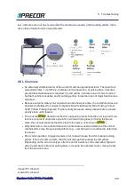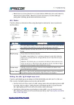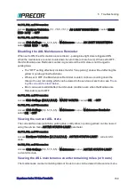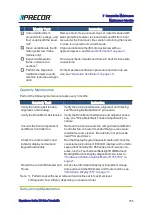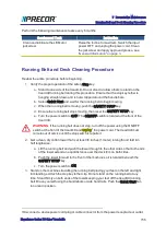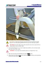
low - indicates an error has occurred but the machine is useable; and 4) pulsing yellow - indic-
ates a loss of major function was detected.
ASL Overview
l
An externally visible indicator of the current machine operational status. There are four
supported states: 1) solid blue - indicates normal operation, 2) pulsing blue - indicates
preventative maintenance is required; 3) solid yellow - indicates an error has occurred
but the machine is useable; and 4) pulsing yellow - indicates a loss of major function was
detected.
l
Because only one status color and state can be shown at a time, the condition states are
prioritized as follows from lowest to highest: Blue Solid (lowest), Blue Pulsing, Yellow
Solid, Yellow Pulsing (highest). Higher priority states are always shown before a lower
priority state, until cleared.
l
The console
UPCA
1
determines the ASL state using inputs from the error log and main-
tenance counter. During active operation (workout in progress) or during the pause
state, the console transmits the ASL state to the lower control board (
LPCA
2
).
l
Only direct error code and maintenance counter data is used to determine the current
machine ASL state. No special algorithms (e.g., user behavior) are utilized to determine
the status.
l
Error code operation: A logged system error code will cause the ASL to begin pulsing
yellow. If the error self-corrects, the ASL will change from pulsing to solid yellow.
Depending on the error code type, after the end of a workout, the solid yellow light will
either revert back to blue (or pulsing blue), or require the operator to do a manual reset
from the service menu.
1
Upper PCA board
2
Lower PCA board
Experience Series 700 Line Treadmills
148
6 Troubleshooting
Summary of Contents for Experience TRM700-16
Page 1: ...Service Manual Experience Series 700 line TRM700 16 Base Treadmill 120 VAC and 240 VAC ...
Page 19: ...Experience Series 700 Line Treadmills 12 1 Introduction General Information ...
Page 104: ...Experience Series 700 Line Treadmills 97 5 Replacement Procedures Drive Belt Replacement ...
Page 172: ...Experience Series 700 Line Treadmills 165 8 Theory of Operation System Wiring Diagram ...
Page 174: ...Experience Series 700 Line Treadmills 167 8 Theory of Operation Exploded View Diagram ...
Page 175: ...Experience Series 700 Line Treadmills 168 8 Theory of Operation Exploded View Diagram ...
Page 176: ...Experience Series 700 Line Treadmills 169 8 Theory of Operation Exploded View Diagram ...
Page 177: ...Experience Series 700 Line Treadmills 170 8 Theory of Operation Exploded View Diagram ...
Page 178: ...Experience Series 700 Line Treadmills 171 8 Theory of Operation Exploded View Diagram ...
Page 179: ...Experience Series 700 Line Treadmills 172 8 Theory of Operation Exploded View Diagram ...
Page 181: ...Experience Series 700 Line Treadmills 174 8 Theory of Operation Parts List ...
Page 182: ...Experience Series 700 Line Treadmills 175 8 Theory of Operation Parts List ...
Page 183: ...Experience Series 700 Line Treadmills 176 8 Theory of Operation Parts List ...

