page 17
C
O
M
M
E
R
C
I
A
L
P
R
O
D
U
C
T
S
D
I
V
I
S
I
O
N
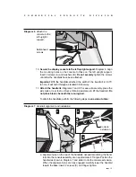
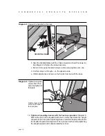
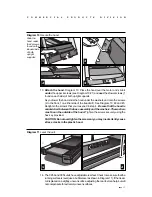
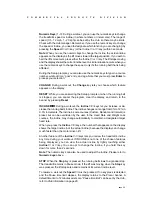
Diagram 10 Secure the hood.
13. Attach the hood. Diagram 10. Place the hood over the motor and slide it
under the upper 4 screws (see Diagram 10 #1) and over the 2 lower screws (1
found on each side) of both upright supports.
As you lower the hood, slide the hood under the washers and onto the screws
(2 in the front, 1 on either side of the treadmill). See Diagram 10, #2 and #3.
Retighten the screws that you loosened in step 4.
Be sure that the hood is
sandwiched between the base assembly and the washers. The washers
must be on the outside of the hood. Tighten the screws securely using the
hex key provided.
CAUTION: Do not overtighten the screws or you may inadvertently cause
stress cracks in the plastic hood.
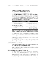
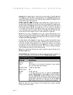
Diagram 11
Level the unit.
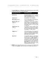
14. The C956 and C954 units have adjustable rear feet. Check to make sure that the
running surface is level (use a bubble level as shown in Diagram 11). If the tread-
mill is placed on a slightly, uneven surface, adjusting the rear feet can help, but will
not compensate for extremely uneven surfaces.
1
3
2
1
Slide the
hood under
the 2 screws
found on the
inboard side
of both
upright
supports.
2
4

