page 14
C
O
M
M
E
R
C
I
A
L
P
R
O
D
U
C
T
S
D
I
V
I
S
I
O
N
9.
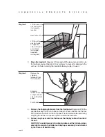
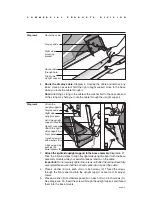
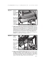
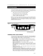
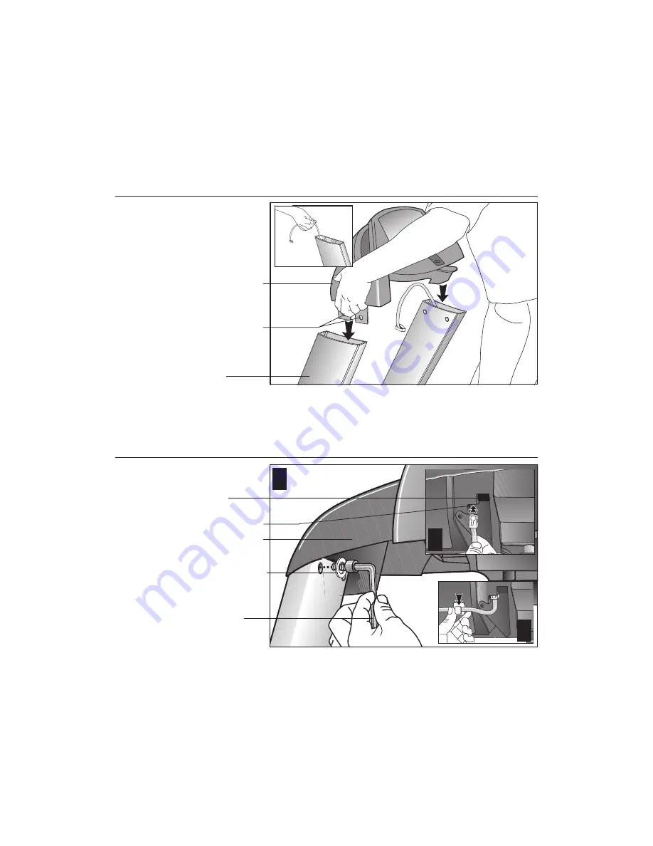
Secure the display console to the upright supports.
Diagram 7.
a.
Make sure that the cable is routed through the top of the upright support.
Have an assistant hold onto the cable (see inset).
Diagram 7
Install the
display console.
Display console
Display console
mounting
brackets
Upright
support
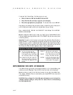
Diagram 8
Secure the
display console.
Tighten the
screws, but
leave room for
adjustments.
1
-inch screws (G)
with washers (D)
Display console
1
3
2
CSAFE
receptacle
Cable receptacle
b.
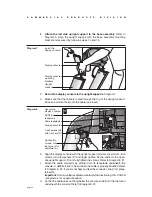
Align the display console with the upright support mounts. Insert two 1-inch
screws (G) with washers (D) and finger tighten. Do the same for the oppo-
site upright support. Do not fully tighten the screws. Refer to Diagram 8, #1.
c.
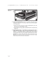
Attach the cable connector by sliding it into its receptacle underneath the
console. A definite “click” is heard when the cable is properly attached. Refer
to Diagram 8, #2. If you do not hear and feel the connector “snap” into place,
reinsert it.
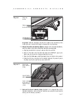
Important:
Do not use the receptacle covered by the plastic plug. This CSAFE
receptacle is for a separate option.
d.
So that the cable does not hang below the console, slide it into the clip found
underneath the console. Refer to Diagram 8, #3.
8.
Attach the
left side upright support to the base assembly.
Refer to
Diagram 6. Align the upright support with the base assembly mounting
bracket and secure it by following steps 7a and 7b.


