background image

700/600 Line Treadmill

Assembly Guide

Summary of Contents for 600 Series

Page 1: ...700 600 Line Treadmill Assembly Guide ...

Page 2: ......

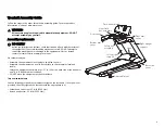
Page 3: ...com We recommend you Assemble the equipment close to where you plan to use it Assemble the equipment on a solid flat surface so that it remains level and stable Locate the equipment a minimum of 19 7 in 0 5 m on each side of the treadmill and 78 in 2 m behind the treadmill DO NOT move the equipment without assistance Torque measurements Use the following torque measurements to tighten the fastener...

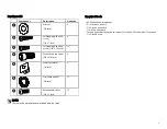
Page 4: ...her 3 8 inch 6 Self tapping pan head screw 1 4 x 1 inch 6 Self tapping pan head screw 1 4 x 75 inch 29 Socket head cap screw 3 8 x 5 8 inch 6 Plastic grommet 1 4 inch 6 Star tooth washer 3 8 inch 12 Button head screw 3 8 x 1 inch 12 7 32 inch hex wrench 1 4 inch hex wrench Torque wrench with tension to at least 25 ft lbs 33 90 Nm with 5 16 inch and 7 32 inch drivers 5 ...

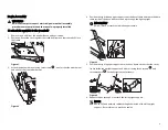
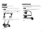
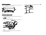
Page 5: ... the front attachment Figure 2 4 Position the right side upright support near the base frame and route the data cable inside of the base side cover and up through the right upright IMPORTANT DO NOT pinch or crush the cable during assembly Figure 3 5 Position the right upright support onto the base frame so that the side cover lip fits inside the upright support and attach it using three screws and...

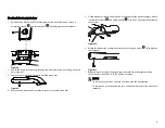
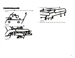
Page 6: ...lly tighten the screws Figure 5 3 Tighten all 12 screws to 25 ft lb 33 90 Nm of torque Tighten the lower upright screws in the order shown in Figure 6 Figure 6 To complete the dash assembly 1 Remove the two screws from the back of the dash cover Remove the dash cover and set it aside with the screws 2 Route the data cable through the right tube of the dash assembly up the back frame and out throug...

Page 7: ...rs from each tread arm 5 Fit the tread arm into the heart rate bar and against the dash assembly Attach it using two screws and two washers Use a hex key to partially tighten the screws Figure 10 6 Attach the underside of each heart rate arm using one screw Fully tighten the fasteners Figure 11 7 Repeat Steps 3 through 6 to attach the other arm and then tighten all six socket head screws to 25 ft ...

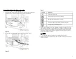
Page 8: ...erminal Green and yellow lead with quick connect terminal AC input cable to the power cable 3 Use the Velcro fasteners to attach the power supply on the right side of the treadmill base Plug the AC input cable into the socket on the power supply 4 Route the DC output cable through the cable ties behind the power supply toward the upright support on your right Bend the cable ties over the DC output...

Page 9: ...ht hand grommet and insert it into the connector inside the panel Use a 7 16 inch torque wrench to tighten the connectors to 30 in lb 3 39 Nm of torque 4 Pass the lower end of the Ethernet cable through the right hand grommet and snap it into the eight pin coupler in the panel 5 Fit the lower ends of any optional console cables into the notch in the upper edge of the panel 6 Replace the panel and ...

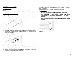
Page 10: ... bottom part of the safety key assembly onto the bottom of the dash assembly and heart rate arms NOTE Flex the plastic to snap it into place 2 Position the top piece of the safety key assembly on top of the bottom part Figure 19 3 Route the cable under the black bar on the safety key assembly and up through the dash Figure 19 4 Attach the top part of the safety key assembly using two screws Figure...

Page 11: ...mets into of the dash arms just above each upright support Figure 21 2 Attach the front arm cover using four screws Figure 22 3 Attach the bottom arm cover using four screws Figure 23 4 Repeat Steps 1 through 3 to attach the covers to the other arm 12 ...

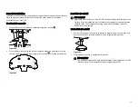
Page 12: ...l the treadmill IMPORTANT Adjust only one rear foot at a time DO NOT extend the adjustable feet more than 3 4 inch 2 cm Adjusting the rear feet cannot compensate for extremely uneven surfaces If you cannot make the running surface level and stable move the treadmill to a level surface To level the treadmill 1 Use a 3 4 inch open end wrench to loosen the jam nuts on the rear feet and adjust as need...

Page 13: ...ered If Then If the belt starts to drift toward the right Slowly and manually turn the right side take up roller mounting bolt clockwise in quarter turn increments until the drifting stops If the belt starts to drift toward the left Slowly and manually turn the right side take up roller mounting bolt counter clockwise in quarter turn increments until the drifting stops Figure 27 3 Increase the spe...

Page 14: ...s might occur if an exerciser steps off the treadmill before the end of a workout and leaves the treadmill running To test Auto Stop 1 Start any workout on the treadmill but DO NOT step onto the running belt 2 Wait two minutes without stepping onto the running belt At this point or shortly beforehand the treadmill should slow to a stop and the console should ask the previous user to confirm that h...

Page 15: ......

Page 16: ...700 600 Line TRM Assembly Guide 305285 101 rev A ENU 2018 Precor Incorporated May 2018 ...

Reviews: