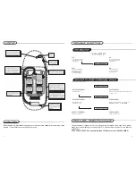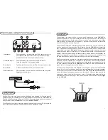
1. Attenuation-
Push this switch in to accept high level RCA inputs (up to 8v) or
direct speaker lead inputs from common grounded (not high
powered) headunits. See diagram below for wiring.
2. Combined Inputs-
Push this switch IN to connect Front and Rear Inputs.
Leave the switch OUT for front/rear fading.
3. Rear Inputs-
For fading rear fill, connect the rear RCAs from your head unit here.
4.Front Inputs-
Connect the front RCAs from your head unit here.
5. After connection-
After connecting Ground, Remote, and Power wires, plug in the
Powerlock connector here.
The next step is to connect the Power, Ground, and Remote wires to your
FRX-456. The
power wire should run from the mounting location through the vehicle to the battery or
power distribution block. Avoid sharp corners, creases, and sharp body parts. When
passing through any metal wall (i.e. firewall etc.), a grommet must be used to prevent the
wire from chafing and shorting to ground.
The ground wire should be of the same gauge as the power wire. As a rule of thumb, use
as short a length of wire as possible. Find a location near the
FRX-456 that is metal (the
floor is ideal) and clean an area about the size of a quarter to bare metal. Drill a pilot hole
in the middle of this area. Be Careful! Inspect the area underneath to be sure you are not
drilling into wires, brake or fuel lines, etc. Terminate the wire with a ring connector and
attach it to the bare metal using a #8 sheet metal screw and washer (not supplied). We
suggest crimping and/or soldering this connection. After the connection is complete, coat
the area with silicone or some similar material to prevent rust from developing.
Finally, the remote wire needs to run to the power amplifier (or antenna remote) lead of the
head unit. This wire supplies a 12 volt signal to the crossover when the main system is
activated. Once you have routed the power, ground, and remote wires through the vehicle,
it is time to connect the wires to the
FRX-456. Be sure that you have not reconnected the
ground cable to the negative post of the battery.
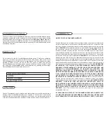
Cut off excess wire and, using wire strippers, strip the power, ground and remote cables
about 1/8 inch. Locate the power, ground, and remote
Powerlock
™
connector (supplied).
On the top of the connector are three slotted screws. With a small flat-bladed screwdriver,
loosen the screws before attempting to insert the cables. After you have inserted the
stripped end of each cable into the connector, secure it by tightening the associated screw.
Check that each connection is tight. If the wires are secure, the connector may be plugged
into the
FRX-456.
8
5
Caution! If you are using a source unit with bridged high powered (or "floating ground")
speaker outputs, a suitable high to low level adapter must be used. We recommend the
Directed Audio Essentials adapter p/n (55020). If you are unsure about your head unit
see your local
PrecisionPower
dealer or call
1-800-62POWER.
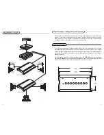
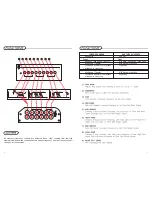
To use Speaker Level Inputs (common ground headunits only), connect RCA plugs to the
front or rear speaker leads as shown, and push IN the Attenuation switch.


