


13
PM-1030V v5 2020-10
Copyright © 2020 Quality Machine Tools, LLC
POWER FEED (Turning & Facing operations)
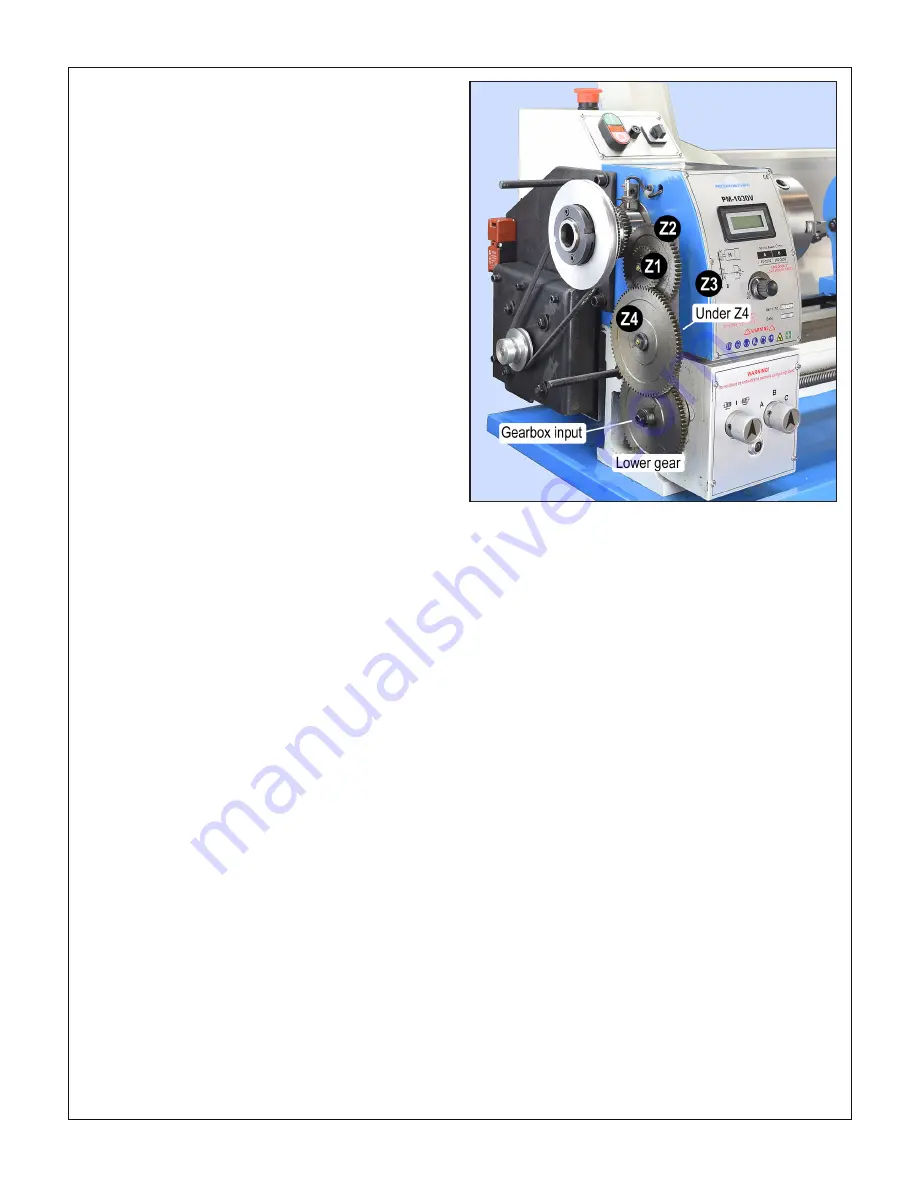
The PM-1030V gearbox is driven by a train of external gears
taking power from the spindle gear, Figure 3-16. The output
from the gearbox is a "two-in-one" leadscrew, with: 1. Threads
(8 TPI), for thread-cutting operations only, and; 2. A full length
key slot.
Only the key slot is active for turning and facing
operations:
it is the source of power for an internally keyed,
smooth-bore worm that slides along the leadscrew as the sad-
dle and apron are driven along the bed (see item #32, apron
components drawing).
To offset the tailstock for taper turning, loosen the tailstock
clamp lever, Figure 3-15, then loosen the clamp screw (M5
set screw) at the tail end of the tailstock. The tailstock can now
be moved forward or backward by adjusting the M8 socket
head cap screws on either side. To move the tailstock to the
back, for instance, the screw on the clamp lever side would be
unscrewed, then the opposing screw would be screwed in to
move the upper assembly. Re-tighten the clamp screw when
the offset is done.
Offsetting the tailstock for a specific taper is not a straight-
forward job; it is a lengthy, iterative process. The same
goes for re-zeroing for normal operations.
A visual indication of the offset is provided by a scale on the
back surface, but this is not a reliable measure for precise
work. In practice, the only way to determine the offset precisely
is to "cut and try' on the workpiece, or scrap stock, homing in
on the correct degree of offset in small increments.
The same issues arise when re-establishing "true zero" of the
tailstock, in other words returning it to the normal axis for rou-
tine operations. One way to avoid cut-and-try is to prepare in
advance a bar of (say) 1" diameter quality ground stock, with
precise center drillings
at both ends (do this by indicating for
zero TIR in a 4-jaw chuck, not in a 3-jaw unless known to be
predictably accurate). The prepared bar can then be installed
between centers and indicated along its length.
Figure 3-17 lists the coarse and fine feed rates available with
two external gear setups. Because the difference between the
two is quite small (1.4/1), many users opt for one or the other
for all their work, saving time by not changing external gears.
The gearbox (A-B-C) provides 2:1 and 4:1 speed choices with-
in each range.
External change gear swapping
The general procedure for this is:
1. Loosen the M8 socket head screw securing the change
gear support bar; swing the support bar down.
In the fol-
lowing steps, note the position and type of all bushings
and washers.
2. Remove the upper and lower gear axles; tap free the exter-
nally keyed bushings.
3. Remove the M6 socket head screw from the gearbox input
shaft.
4. Install the selected gear pairs on the upper and lower keyed
bushings; install the selected lower gear on the gearbox
input shaft, bearing in mind the
location of the internally
keyed bushings
, above or below the gears, see Figures
3-20, 3-21 and 3-22.
Figure 3-16
External change gears
5. Re-install the upper and lower gear axles, loosely threading
them into the T-nuts at the back of the support bar.
6. Bring the lower gear pair into mesh with the gearbox input
gear; tighten the lower gear axle in its T-nut.
7. Bring the upper gear (or gear pair) into mesh with the lower;
tighten the upper gear axle in its T-nut.
8. Check, making minor adjustments to, the mesh of all gears
in the train (see note below).
9. Swing the gear support bar up to mesh the upper gear with
the spindle gear; tighten the M8 socket head screw secur-
ing the support bar.
10. Lubricate the gears using (say) lithium grease.
How to gauge “correct mesh”
Some users go by feel and
intuition, others use a paper feeler gauge. The mesh is good if
a scrap of 0.004” printer paper can be run between the gears
with definite resistance.
Difficulty re-installing gears?
When new, the gears may be a tight fit on the exter
-
nally keyed bushings. Check for burrs on the bush-
ings, dressing with a fine file if necessary. The gear
bores may also need de-burring with Scotch-Brite, or
other fine-grit abrasive (or using a rod-shape diamond
hone). Aim for an easy push fit of all gears on both
bushings.
?