PD6800-0L1 Loop-Powered Process Meter
Instruction Manual
44
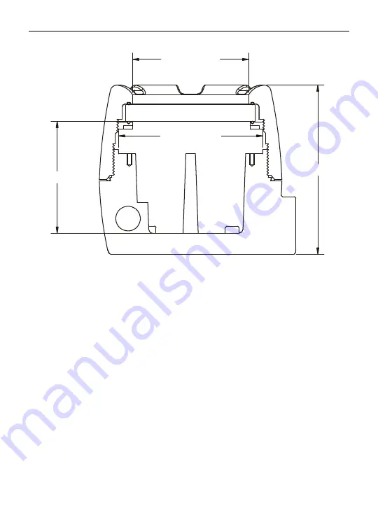
Figure 10. Enclosure Dimensions – Side Cross Section View
3.35 [85.0]
4.15 [105.5]
3.22 [81.9]
4.86 [123.5]
Page 1: ...SafeTouch Through Glass Button Programming Password Protection 32 Point Square Root or Exponential Linearization Open Collector Alarm Output Loop Powered or External DC Powered Backlight Standard HART...
Page 2: ...cision Digital Corporation shall not be held liable for damages resulting from such improper use Failure to follow installation guidelines could result in death or serious injury Make sure only qualif...
Page 3: ...med to show any combination of numbers and letters up to seven characters long for use as engineering units the process identification tag or a display for the calculated volume when using for level a...
Page 4: ...Operation 17 SafeTouch Button Tips and Troubleshooting 17 Buttons and Display 18 Main Menu 20 Setting Up the Meter SETUP 21 Setting Numeric Values 22 Setting the Level Decimal Point DECIMAL 22 Main Me...
Page 5: ...42 MOUNTING DIMENSIONS 43 QUICK USER INTERFACE REFERENCE 45 EU DECLARATION OF CONFORMITY 47 Table of Figures Figure 1 Connector Board 12 Figure 2 Connections without Backlight 13 Figure 3 Connections...
Page 6: ...are stored until reset by the user or until power to the meter is turned off PASSWORD Programmable password restricts modification of programmed settings NON VOLATILE MEMORY All programmed settings ar...
Page 7: ...ut 1 Input 2 4 20 mA 0 10 mA MAXIMUM VOLTAGE DROP Without Backlight or with Externally Powered DC Powered Backlight With Loop Powered Backlight 3 0 VDC 20 mA 6 0 VDC 20 mA EQUIVALENT RESISTANCE 150 20...
Page 8: ...749 IECEx Ex d IIC T6 Gb Ex tb IIIC T85 C Db IP68 Ta 40 C to 75 C Certificate number IECEx SIR 10 0056X Special Conditions for Safe Use Use suitably certified and dimensioned cable entry device and or...
Page 9: ...I 3 V 0 15 80 MHz 1 kHz 80 AM SAFETY INFORMATION WARNINGS Read complete instructions prior to installation and operation of the meter Installation and service should be performed only by trained servi...
Page 10: ...onnectors remove the 2 captive screws then disconnect the ribbon cable from the display module and set the display module aside Unpacking Remove the meter from box Inspect the packaging and contents f...
Page 11: ...the screw clockwise until the screw contacts the meter Turn the screw an additional 1 4 to 1 2 turn to secure the cover Caution Excess torque may damage the threads and or wrench Connections WARNINGS...
Page 12: ...powering backlight from external supply OUTPUT NPN open collector output positive OUTPUT NPN open collector output negative RESET Contact closure alarm acknowledge pull up to 3 VDC RESET Contact clos...
Page 13: ...e connected The 4 20 mA input with no backlight has a maximum voltage drop of 3 V and is wired as shown in Figure 2 The loop powered backlight configuration requires a total maximum voltage drop of 6...
Page 14: ...light The backlight circuit will draw 25 mA in addition to the loop circuit External Acknowledge Connection External acknowledge connections are made to two terminals labeled RESET Connect to a contac...
Page 15: ...PD6800 0L1 s amplifying components use care not to wire incorrectly or exceed output ratings A diode such as 1N4000 series will provide protection from relay transients Figure 6 Connection to Device...
Page 16: ...ds Overview Setup and programming is done through the infrared through glass SafeTouch buttons or using the mechanical buttons when uncovered There are two slide switches located on the connector boar...
Page 17: ...e re enabled after 60 seconds of inactivity SafeTouch Button Tips and Troubleshooting The SafeTouch Buttons are designed to filter normal levels of ambient interference and to protect against false tr...
Page 18: ...0L1 Loop Powered Process Meter Instruction Manual 18 Buttons and Display Button Symbol Description Symbol Status Menu Tank Level Indicator Right arrow Reset Up arrow Display Enter MENU RESET DISPLAY...
Page 19: ...ng displayed see Up Display Button below Press the Right arrow button to move to the next digit or decimal position during programming Press Right to go backward through most selection menus Up Displa...
Page 20: ...p Arrow button to scroll through the main menu Hold MENU at any time to exit and return to Run Mode Changes made to settings prior to pressing ENTER are not saved Press the MENU button during Programm...
Page 21: ...ank indicator full and empty values 4 Bottom display selection Press the ENTER button to access any menu or press UP arrow button to scroll through choices Hold MENU at any time to exit and return to...
Page 22: ...s made to settings prior to pressing ENTER are not saved Press the MENU button during Programming Mode to return to return to the previous menu selections Setting the Level Decimal Point DECIMAL Decim...
Page 23: ...SAVE Save Save entered scale parameters SPN ERR Span Error Scale point 1 and 2 span error PERCENT Percent Scale the tank indicator full and empty values 0 PCT 0 Percent Set the tank empty value 100 P...
Page 24: ...ing units display value Do the same for input 2 After entering the display 2 value confirm the new scale by pressing ENTER at the Save menu A signal source is not needed to scale the meter simply prog...
Page 25: ...The display includes a 20 segment tank level indicator This menu sets full and empty values in engineering units for the tank level indicator This value may differ from the 20 mA full scale and 4 mA e...
Page 26: ...numeric characters programmed for identification e g TANK 3 or for engineering units e g GALLONS Volume is a separate second scale of the input process variable This is configured in Volume Display Sc...
Page 27: ...setting that includes a tag will require the tag to be entered The fully alphanumeric values for the tag are set using the RIGHT button to select the digit the UP and RIGHT arrow buttons to select th...
Page 28: ...structions on how to program numeric values see Setting Numeric Values page 22 Record the password for future reference If appropriate it may be recorded in the space provided Model Serial Number Pass...
Page 29: ...tered the meter displays the message UNLOCKD unlocked and the protection is disabled until a new password is programmed If the password entered is incorrect the meter displays the message LOCKED and r...
Page 30: ...ess the Advanced Features Menu by pressing ENTER at the ADVANCE menu in the Main Menu defined on page 20 The Advanced Features Menu is used to select 1 Open collector output configuration OUTPUT 2 Inp...
Page 31: ...noise filter to medium setting HI Filter High Set noise filter to high setting OFF Filter Off Disable noise filter VOLSCAL Volume Scale Scale the volume display vOl DECIMAL Volume Decimal Set the dec...
Page 32: ...rror SPAN Error Span Error with calibration point 1 and 2 span MULTIPT Multipoint Set level display multipoint linearization DISABLE Disable Disable multipoint linearization ENABLE Enable Enable multi...
Page 33: ...ile the level indicator is at or above the alarm point When the alarm is enabled for volume and the alarm set point has been reached the bottom display will flash alternating between its normal displa...
Page 34: ...the input signal are displayed im mediately Volume Display Scaling VOLSCAL Volume may be scaled as a function of the level display It may use up to 32 point linearization The multi point linearization...
Page 35: ...35 Level Input Live Signal Calibration LVL CAL The meter can be calibrated using a current source instead of scaling This process will override previously programmed scaling of the level display The u...
Page 36: ...he meter Allow the meter to warm up for at least 15 minutes before performing the calibration procedure Press MENU navigate to ADVANCE and press enter to access the Advanced Features Menu Press the UP...
Page 37: ...age 35 menus to include a Number of Points NO PTS parameter before entering Input 1 32 point linearization can be used to linearize the display for non linear signals Information INFO The Information...
Page 38: ...tion Button Symbol Description Press to Enter or Exit Programming Mode Used to Reset Maximum and Minimum Values Press to Cycle Displaying Maximum Value Minimum Value and Input Current in mA Press to R...
Page 39: ...word MINIMUM on the bottom display and the minimum value reached on the top display Pressing the RESET button while either of these values is displayed will reset that value to the current display val...
Page 40: ...art the setup process from the factory defaults Instructions to load factory defaults Enter the Advanced Features Menu Press and hold Reset button when INFO is shown For information on navigating to t...
Page 41: ...ic Setup Level Decimal Point DECIMAL 1111 1 Input 1 INPUT 1 4 000 mA Display 1 DSPLY 1 0 0 Input 2 INPUT 2 20 00 mA Display 2 DSPLY 2 100 0 Tank Indicator 0 0 PCT 0 0 Tank Indicator 100 100 PCT 100 0...
Page 42: ...r 999999 Check level display within volume scale range of 9999999 and 999999 Display response is too slow Check filter setting to see if it can be lowered to LO or OFF If the display locks up or the m...
Page 43: ...PD6800 0L1 Loop Powered Process Meter Instruction Manual 43 MOUNTING DIMENSIONS All units inches mm Figure 9 Enclosure Dimensions Front View 3 35 85 1 2 25 57 1 0 32 8 2 5 65 143 5 5 25 133 4...
Page 44: ...PD6800 0L1 Loop Powered Process Meter Instruction Manual 44 Figure 10 Enclosure Dimensions Side Cross Section View 3 35 85 0 4 15 105 5 3 22 81 9 4 86 123 5...
Page 45: ...Function MENU Go to programming mode or leave programming Hold for 5 seconds to enter Advanced Features menu directly RIGHT Arrow Move to next digit Go to previous menu or alphanumeric char acter sele...
Page 46: ...PD6800 0L1 Loop Powered Process Meter Instruction Manual 46...
Page 47: ...007 EN 60079 31 2009 EN 61000 6 4 2004 EN 61010 1 2001 and EN 61326 2006 are no longer harmonized The requirements of these standards have been checked against the harmonized standard EN 55022 2010 EN...
Page 48: ...9 or 508 655 7300 Fax 508 655 8990 Email support predig com For Sales Support Call 800 343 1001 or 508 655 7300 Fax 508 655 8990 Email sales predig com For the latest version of this manual please vis...