


7
3.0
Making Path Loss Measurements
The Model 5500 Receiver measures absolute signal strength of CW signals at the antenna input port. Relative
path loss measurements can easily be made by selecting a reference location and then moving the receiver to
different locations while noting the change in received signal strength. To measure actual path loss, the user
must take into account the gain of the antennas being used on both the transmitter and receiver and the output
power of the transmitter.
The Model 5500 Receiver is a single conversion receiver with an intermediate frequency of 90MHz. Because of
the bandwidth of the SAW filter, there is very little attenuation of signals in the adjacent channel (30 kHz).
Signals that are 60kHz from the receiver frequency are attenuated by more than 40dB. Because of this
limitation, the user should not conduct tests in a channel adjacent to a strong signal.
When using the receiver with the Model 5700 Transmitter, the following procedure can be used to setup the
equipment to make relative path loss measurements.
•
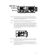
Install the supplied cable between a serial port on the PC/laptop and the serial port on the
receiver.
•
Install the antenna for the proper band and turn the receiver on.
•
Start the RXScan software. Enter the frequencies or channels that you would like to scan and
then initiate the scan. Information on controlling the receiver with the RXScan software can be
found in appendix A.
•
Using the spectrum display or the spreadsheet output of the RXScan software,
choose a test frequency. Tune the receiver to the test frequency.
•
Set up the test transmitter to the test frequency using the procedures outlined in Section 8 of this
manual. The RXScan software can also be used to set up the transmitter. See Appendix A of
this document.
•
Install the 30dB attenuator on the RF OUT port of the test transmitter. (An attenuator is
provided when the Receiver and Transmitter are purchased as a system). Connect a coax cable
from the attenuator to the antenna input of the receiver for the correct band.
Caution: Always
use the attenuator when connecting the transmitter directly to the receiver. Too much
RF power applied to the receiver could damage the low noise amplifier.
•
Adjust the AMPL ADJ control on the transmitter until the receiver measures 30dB lower then
the output power you would like at the transmitter antenna base.
•
Connect the test transmitter to the test antenna.
•
Begin path loss measurements.
4.0
Controlling the Receiver Remotely
The receiver can be controlled by a PC or embedded controller via the RS232 interface. The RXScan software
included with the receiver can be used to control the receiver for most applications. Procedures in this section
also describe control with terminal emulation software on a PC or laptop computer.