background image

ALIMENTATION A DECOUPAGE

Type 2220

SOMMAIRE

Avertissements  . . . . . . . . . . . . . . . . . . . . . . . . . . . . . . . . .  24
Consignes de sécurité. . . . . . . . . . . . . . . . . . . . . . . . . . . .  26
Déclaration de conformité. . . . . . . . . . . . . . . . . . . . . . . . .  28
Démontage du SYSTEME 2200  . . . . . . . . . . . . . . . . . . . .  29
Applications. . . . . . . . . . . . . . . . . . . . . . . . . . . . . . . . . . . . 30
Caractéristiques techniques  . . . . . . . . . . . . . . . . . . . . . . .  30
Montage  . . . . . . . . . . . . . . . . . . . . . . . . . . . . . . . . . . . . . .  30
Entrée  . . . . . . . . . . . . . . . . . . . . . . . . . . . . . . . . . . . . . . . .  31
Sortie . . . . . . . . . . . . . . . . . . . . . . . . . . . . . . . . . . . . . . . . . 31
Spécifications électriques . . . . . . . . . . . . . . . . . . . . . . . . .  31
Référence de commande  . . . . . . . . . . . . . . . . . . . . . . . . .  33
Schéma de principe  . . . . . . . . . . . . . . . . . . . . . . . . . . . . .  33

23

22

Summary of Contents for 2220

Page 1: ...loop powered and universal isolators featuring linearisation inversion and scaling of output signals PC or front programmable modules with universal options for input output and supply This range offers a number of advanced features such as process calibration linearisation and auto diagnosis A wide selection of transmitters for DIN form B mounting and DIN rail modules with analogue and digital bu...

Page 2: ...INDHOLDSFORTEGNELSE Advarsler 2 Sikkerhedsregler 3 Overensstemmelseserklæring 5 Adskillelse af SYSTEM 2200 6 Anvendelse 7 Teknisk karakteristik 7 Montering 7 Indgang 7 Udgang 8 Elektriske specifikationer 8 Bestillingsskema 10 Blokdiagram 10 1 ...

Page 3: ...g sideskiltet For moduler som er permanent tilsluttet farlig spænding gælder For sikringens maksimale størrelse er 10 A og skal sammen med en afbryder placeres let tilgængelig og tæt ved modulet Afbryderen skal mærkes således at der ikke er tvivl om at den afbryder spændingen til modulet 3 2 ADVARSEL Dette modul er beregnet for tilslutning til livsfarlige elektriske spændinger Hvis denne advarsel ...

Page 4: ...NG OG JUSTERING Under kalibrering og justering skal måling og tilslutning af eksterne spændinger udføres i henhold til denne manual og teknikeren skal benytte sikkerheds mæs sigt korrekte værktøjer og instrumenter BETJENING UNDER NORMAL DRIFT Operatører må kun indstille eller betjene modulerne når disse er fast installeret på forsvarlig måde i tavler el lignende så betjeningen ikke medfører fare f...

Page 5: ...MONTERING 2220 benytter en standard 11 polet sokkel og kan monteres i alle stillinger For bedste luftafkøling anbefales det at montere enheden i lodret stilling og holde en mindre afstand 10 mm til nabomoduler INDGANG Standard forsyningsspændinger i henhold til specifikationerne Galvanisk isola tion sikres af den dobbelt isolerende sikkerhedstransformator 7 6 ADSKILLELSE AF SYSTEM 2200 Modulets ba...

Page 6: ...p 2 2 Amp ELEKTRISKE SPECIFIKATIONER Specifikationsområde 20 C til 60 C Fælles specifikationer Egetforbrug max 4 W Isolation test drift 3 75 kVAC 250 VAC Transformator EN 60742 Temperaturkoefficient 0 05 C Virkning af forsyningsspændings ændring 10 30 mV Transient stabilitet 10 max belast 250 mV EMC immunitetspåvirkning 0 5 Relativ luftfugtighed 95 RH ikke kond Mål HxBxD 80 5 x 35 5 x 84 5 mm Kaps...

Page 7: ...w to dismantle SYSTEM 2200 17 Applications 18 Technical characteristics 18 Mounting 18 Input 18 Output 19 Electrical specifications 19 Order 21 Block diagram 21 11 10 BESTILLINGSSKEMA BLOKDIAGRAM Udgang Type Version 2220 110 VAC A 230 VAC B 24 VAC D 120 VAC F Speciel 5 24 V 0 24 VDC 1 15 VDC 2 12 VDC 3 5 VDC 4 ...

Page 8: ...s manual must be examined carefully Only qualified personnel technicians should install this module If the equipment is used in a manner not specified by the manufacturer the protection provided by the equipment may be impaired WARNING Until the module is fixed do not connect hazardous voltages to the module The following operations should only be carried out on a disconnected module and under ESD...

Page 9: ...o mount operate and also troubleshoot technically correct and in accordance with safety regulations Operators being familiar with the contents of this manual adjust and operate the knobs or potentiometers during normal operation RECEIPT AND UNPACKING Unpack the module without damaging it and make sure that the manual always follows the module and is always available The packing should always follo...

Page 10: ...uck 17 Picture 1 Dismantlement of back plate and housing Picture 2 Removal of knobs Picture 3 Removal of PCBs for adjustment of DIP switches and replacement of jumpers DECLARATION OF CONFORMITY As manufacturer PR electronics A S Lerbakken 10 DK 8410 Rønde hereby declares that the following product Type 2220 Name Switchmode power supply is in conformity with the following directives and standards T...

Page 11: ...ction Thermal overload protection Standard 11 pole relay socket APPLICATIONS General power supply for smaller measurement systems requiring fixed stabilized 24 VDC or supply for any other sensors transmitters or as a general variable power supply 5 to 24 VDC Two units may be connected in series for plus minus or higher output voltage TECHNICAL CHARACTERISTICS The unit is based on secondary switchm...

Page 12: ...l VNIIM Cert No See www prelectronics com Observed authority requirements Standard EMC 2004 108 EC EN 61326 1 LVD 2006 95 EC EN 61010 1 PELV SELV IEC 364 4 41 and EN 60742 20 ORDER BLOCK DIAGRAM Output Type Version 2220 110 VAC A 230 VAC B 24 VAC D 120 VAC F Special 5 24 V 0 24 VDC 1 15 VDC 2 12 VDC 3 5 VDC 4 ...

Page 13: ...ements 24 Consignes de sécurité 26 Déclaration de conformité 28 Démontage du SYSTEME 2200 29 Applications 30 Caractéristiques techniques 30 Montage 30 Entrée 31 Sortie 31 Spécifications électriques 31 Référence de commande 33 Schéma de principe 33 23 22 ...

Page 14: ... ce module en marche L installation de ce module est réservée à un personnel qualifié techniciens Si la méthode d utilisation de l équipement diffère de celle décrite par le fabricant la protection assurée par l équipement risque d être altérée AVERTISSEMENT Tant que le module n est pas fixé ne le mettez par sous tensions dangereuses Les opérations suivantes doivent être effectuées avec le module ...

Page 15: ...ualifiées qui sont capables de monter et de faire fonctionner un appareil et d y rechercher les pannes tout en respectant les règles de sécurité Les opérateurs connaissant le contenu de ce guide règlent et actionnent les boutons ou les potentiomètres au cours des manipulations ordinaires RECEPTION ET DEBALLAGE Déballez le module sans l endommager Le guide doit toujours être disponible et se trouve...

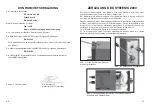
Page 16: ...veuillez vérifier que les fils ne sont pas coincés 29 Figure 1 Séparation de la face arrière et du boîtier Figure 2 Retrait des boutons Figure 3 Extraction de la carte à circuits imprimès pour le réglage des commutateurs et le remplacement des cavaliers DECLARATION DE CONFORMITE En tant que fabricant PR electronics A S Lerbakken 10 DK 8410 Rønde déclare que le produit suivant Type 2220 Nom Aliment...

Page 17: ... une tension stabilisée La tension de sortie peut être réglée dans la gamme de 5 à 24 Vcc Le 2220 permet la connexion en série de 2 modules pour obtenir une alimentation bipolaire ou pour obtenir une tension de sortie plus élevée CARACTERISTIQUES TECHNIQUES Le 2220 est basé sur la technologie du découpage secondaire assurant une sortie réglable avec un rendement optimal La tension d isolation de t...

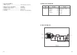
Page 18: ... homologations Standard CEM EMC 2004 108 CE EN 61326 1 DTB 2006 95 CE EN 61010 1 PELV SELV IEC 364 4 41 et EN 60742 32 REFERENCE DE COMMANDE SCHEMA DE PRINCIPE Sortie Type Version 2220 110 Vca A 230 Vca B 24 Vca D 120 Vca F Spéciale 5 24 V 0 24 Vcc 1 15 Vcc 2 12 Vcc 3 5 Vcc 4 ...

Page 19: ...20 INHALTSVERZEICHNIS Warnung 36 Sicherheitsregeln 38 Konformitätserklärung 40 Zerlegung des SYSTEMs 2200 31 Anwendung 42 Technische Merkmale 42 Montage 42 Eingang 42 Ausgang 43 Elektrische Daten 43 Bestellangaben 45 Blockdiagramm 45 35 34 ...

Page 20: ...brauch genommen wird Nur qualifizierte Personen Techniker dürfen dieses Modul installieren Wenn das Modul nicht wie in diesem Handbuch beschrieben benutzt wird werden die Schutzeinrichtungen des Moduls beeinträchtigt WARNUNG Vor dem abgeschlossenen festen Einbau des Moduls darf daran keine gefährliche Spannung angeschlossen werden und folgende Maßnahmen sollten nur in spannungslosem Zustand des Mo...

Page 21: ...hend der eingegangenen Verkaufs vereinbarungen existieren können 39 SICHERHEITSREGELN DEFINITIONEN Gefährliche Spannungen sind definitionsgemäß die Bereiche 75 1500 Volt Gleichspannung und 50 1000 Volt Wechselspannung Techniker sind qualifizierte Personen die dazu ausgebildet oder angelernt sind eine Installation Bedienung oder evtl Fehlersuche auszuführen die sowohl technisch als auch sicherheits...

Page 22: ...n wenn die hintere Abdeckplatte und das Gehäuse zusammengefügt werden 41 Abb 1 Lösen der hinteren Abdeck platte vom Gehäuse Abb 2 Entfernen von Drehknöpfen Abb 3 Herausnehmen der Platine zur Veränderung von Schaltern und Überbrückern KONFORMITÄTSERKLÄRUNG Als Hersteller bescheinigt PR electronics A S Lerbakken 10 DK 8410 Rønde hiermit für das folgende Produkt Typ 2220 Name Schaltmodus Spannungsver...

Page 23: ... im Bereich von 5 bis 24 VDC eingestellt werden 2 Geräte können für eine Plus Minus Versorgung oder für eine höhere Aus gangsspannung in Serie geschaltet werden TECHNISCHE MERKMALE Das Gerät basiert auf einer sekundären Schaltmodus Technologie womit ein justierbarer Ausgang mit minimalem Leistungsverlust erreicht wird Die Isola tionsprüfspannung zwischen Eingang und Ausgang beträgt 3 75 kVAC Das G...

Page 24: ...ngehaltene Richtlinien Norm EMV 2004 108 EG EN 61326 1 LVD 2006 95 EG EN 61010 1 PELV SELV IEC 364 4 41 und EN 60742 44 BESTELLANGABEN BLOCKDIAGRAMM Ausgang Typ Version 2220 110 VAC A 230 VAC B 24 VAC D 120 VAC F Speziell 5 24 V 0 24 VDC 1 15 VDC 2 12 VDC 3 5 VDC 4 ...

Page 25: ...r vous l assurance de la meilleure qualité PR electronics A S verfügt über ein breites Produktprogramm an analogen und digitalen Signalverarbeitungsmodule für die in dustrielle Automatisierung Dieses Programm umfasst Displays Temperaturtransmitter Ex und galvanische Signaltrenner und Universalgeräte Sie können unsere Geräte auch unter extremen Einsatzbedingungen wie elektrisches Rauschen Erschütte...

Reviews: