


HEA-
XX
-HB-4
V
IA
L
ITE
HD
SATCOM6
H
ANDBOOK
15
5.5
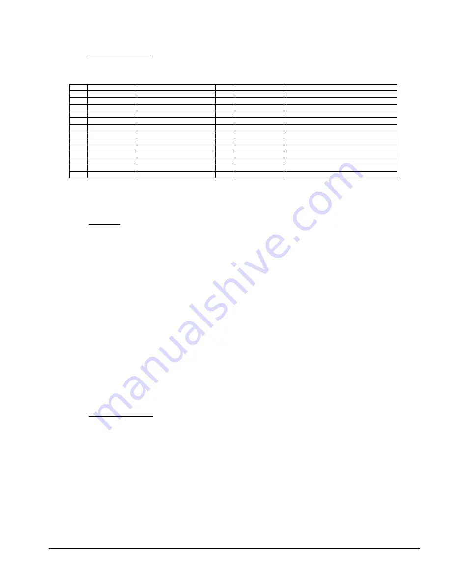
External D25 connector
The external D25 connector provides access to serial interface if serial digital cards are installed in slot 3 or 6. Refer to the serial
digital cards handbook for more information. Dry relay contacts to indicate alarms are also available.
Pin
Pin description
Description
Pin
Pin description
Description
1
GND
14
RX 422 OUT- 6
RS422 interface
– SLOT6
2
RX 422 OUT+ 3
RS422 interface
– SLOT3
15
TX 232 IN 6
RS232 interface
– SLOT6
3
TX 422 IN+ 3
RS422 interface
– SLOT3
16
RX232 OUT 6
RS232 interface
– SLOT6
4
RX 422 OUT- 3
RS422 interface
– SLOT3
17
GND
5
TX 422 IN- 3
RS422 interface
– SLOT3
18
RTS 6
RTS
– SLOT6
6
RX232 OUT 3
RS232 interface
– SLOT3
19
RELAY 1
Dry relay contact (NO
– normally open)
7
TX 232 IN 3
RS232 interface
– SLOT3
20
GND
8
RTS 3
RTS
– SLOT3
21
RELAY 2
Dry relay (COM
– common)
9
GND
22
VCC
10
GND
23
RELAY 3
Dry relay contact (NC
– normally closed)
11
TX 422 IN+ 6
RS422 interface
– SLOT6
24
EXT V+
External power +
12
RX 422 OUT+ 6
RS422 interface
– SLOT6
25
EXT V-
External power -
13
TX 422 IN- 6
RS422 interface
– SLOT6
Table 8 Normal Pin-out of the D25 connector, may differ for some special applications, see cabinet specific handbook
NOTE: Relay contacts are available only if SNMP or SUMMARY ALARM card are fitted.
NOTE: Check jumpers J11 and J21 before connecting D25.
5.6
Using LNBs
5.6.1
Internal LNBs (up to two LNB power cards may be fitted to the SATCOM6)
1.
Make sure that J2 and J3 jumpers are not populated.
2.
Place the LNB unit in slot 7 or slot 8. Configure the LNB, for details refer to the LNB manual. The LNB card in slot 7
supplies voltage to slots 1-3, and the LNB card in slot 8 supplies voltage to slot 4-6.
3.
Using jumpers J11 and J21 connect the LNB to the modules. Use J11 if an optical receiver is used or J21 for a transmitter.
J11 in ‘POWER’ position connects the power from the LNB to the BUC FEED pin of the receiver. J21 connects the power
from LNB to the LNB FEED pin of the transmitter.
5.6.2
External LNB, power routed via mother board
If an external power supply is used instead of LNB units follow this procedure:
1.
Connect power to the J5 connector
2.
By closing J2 jumper the power is routed to the output of the LNB1 internal module (slot 7). Closing J3 jumper routes the
power to the output of the LNB2 module (slot 8). Before closing one of the jumpers make sure that relevant slots are not
populated.
3.
Using jumpers J11 or J21 route the power to the appropriate slots
– refer to ‘Internal LNBs’ section above for more details.
NOTE: Do not exceed voltage or current rating of modules, higher voltage can cause permanent damage. The voltage range of
LNA/LNB feeds is 0 to +28V and for BUC feeds it is -36 to +36V. Please check the handbook specific to the module you are using.
5.6.3
External LNB/BUC, using bias tee modules
It is possible to provide a LNB/BUC power using separate bias Tee module fixed in the base of the SATCOM6. Wiring and other
details of these bias Tees will be shown in the cabinet specific handbook.
5.7
Module Interface ratings
Where relevant please consult module handbooks for the individual modules you are using in each slot.
5.7.1
Logic interface, TTL 5V
Absolute maximum voltage rating
-0.5 to +5.5V
No damage
Input, Logic Low (max)
<0.8V
Input, Logic High (min)
>2.0V
Output, Logic Low (max)
<0.4V no load
Output, Logic High (min)
>4.8V no load
Drive capability
1k ohms
Short circuit protection
No