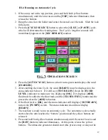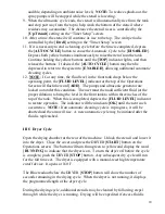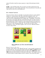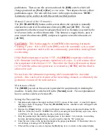
7
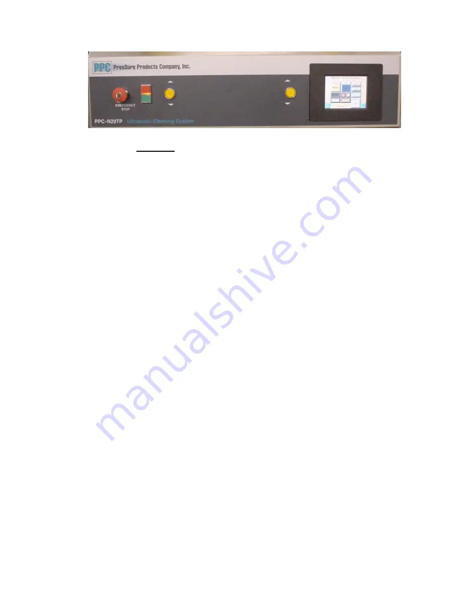
II.5 Control Panel
FIG.
2:
O
PERATOR
C
ONTROL
P
ANEL
The operator control panel contains the following features:
ON/OFF (
I/O
) buttons and power indicator
Dual buttons for lowering or manually raising the arm
Touch screen operator interface panel
[EMERGENCY STOP]
button with key lockout
When pushed in, the
[EMERGENCY STOP]
removes all power to the machine
with the exception of the switch itself and the power control relay. This button
should be pushed only in an emergency when it is necessary to deenergize the entire
machine. When pushed, it removes power from the Programmable Logic Controller
(PLC). Removal of PLC power will cause some operational switch settings to be
reset to their default states when power is restored. Therefore it should not be used
for routine shutdowns. The ON/OFF buttons should be used for this purpose.
II.6 Part Support Arm
The PPC-N29TP is designed to handle 29” x 29” self-tensioning frames. For the
cleaning of other stencil dimensions, boards, or other components, custom tools are
available from PresSure Products upon request.


