


15
4-4.3. MAIN AMPLIFIER
The main amplifier employs class AB amplification for maximum efficiency. The
signal provides approximately 11 dB of gain in the 25 MHz frequency band. The
output from the main amplifier is typically 30 watts. The amplifier operates on +27
Vdc, and a bias voltage of +5 Vdc, and is mounted directly on a heat sink. The
alarm logic controls the +5 Vdc bias voltage that shuts down the amplifier.
4-4.4. ALARM MONITORING AND CONTROL
In the amplifier, all normal variations are automatically compensated for by the
loop control circuit. However, when large variations occur beyond the adjustment
range of the loop control, a loop fault will occur. The alarms are output via a
21WA4 D-sub connector on the module for subsequent remote monitoring.
4-4.5. LOOP CONTROL CIRCUIT
The primary function of the loop control circuit is to reduce the spurious emissions
of the RF signal at all amplifier stages. The loop control circuit controls internal
amplifier parameters of all amplifier stages, thereby optimizing spurious
emissions.
4-5. AMPLIFIER MODULE COOLING
Each amplifier module is contained within a thermally conductive finned chassis
which, when properly cooled with external fans, will provide sufficient cooling to
maintain the amplifier within the specified operating temperature range.
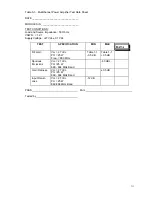
4-6. POWER DISTRIBUTION
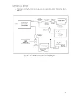
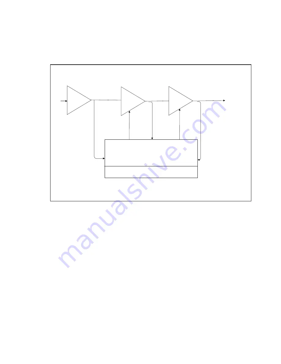
Figure 4-1. G3L-800-25-001 Multichannel Power Amplifier Functional Block
Diagram
LOOP CONTROL CIRCUIT
RF
IN
Control
Control
32 dB
Gain
11 dB
Gain
Three Stage
Driver
Main Amp
RF
OUT
ALARM CIRCUIT
Predriver
13.5 dB
Gain