


43
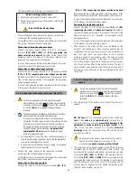
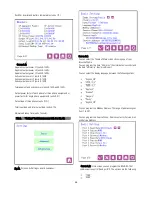
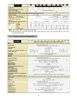
7. DESCRIPTION OF THE CONTROL PANEL.
7.1. CONTROL PANEL PARTS.
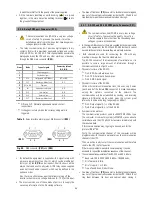
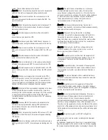
(1)
LED indicators:
(a)
Rectifier input voltage OK (green).
(b)
Equipment on bypass (orange).
(c)
Inverter is working (green).
(d)
Equipment running from batteries -mains failure- (red).
(e)
In case of any alarm of the equipment (red).
(2)
Graphic Display.
(3)
Keyboard
ENT
«Enter» key. Confirmation of orders, program values (or
other specified functions)
«Left» key for submenu navigation, or cursor displacement.
«Right» key for submenu navigation, or cursor displacement.
«Up» key for menu page navigation, or digit modification.
«Down» key menu page navigation, or digit modification.
ESC
«Escape» key. Return to main screen, cancel/finish
programming (or other specified functions).
Fig. 40.
Control panel parts
7.2. BASIC FUNCTIONS OF THE SYNOPTIC KEYPAD.
• Through keys advance
(
)
and return
(
)
, there is access to
all the menus of the LCD panel, being able to move from one to
another.
• Through keys right
(
)
or left
(
)
, there is access to the screens
of all the submenus of the LCD panel, being able to move from
one to another with themselves.
• Key
(ENT)
, has different purposes depending on the menu we
are:
Setting values. Press key
(ENT)
to activate the setting
function, the figures in the screen blink. With keys
(
)
-
(
)
the character to set is selected and with keys
(
)
-
(
)
the
value is selected. To confirm press
(ENT)
. Next field will
blink, to continue doing settings proceed in the same way
or press
(ESC)
to return to no-setting situation.
Validation of orders or commands.
• When pressing key
(ESC)
from any screen of any submenu, it is
gone back to previous screen, unless we are in any screen of
«Parameters»
menu and setting any of them. If so, the first
pulsation of key
(ESC)
will stop blinking the value, and second
one will go back to main screen.
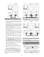
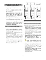
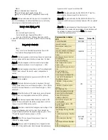
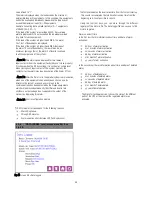
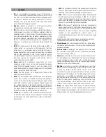
• Notes related with the screen map (see Fig. 41):
Some screens have a certain number of «
–
» characters.
Each one of it, means one character, so the maximum length
of the field will be determined by the quantity of them.
Each screen is labelled with a number located in its right
bottom corner. It is only included as a mere reference for its
next description and explanation.
Fig. 41. Display messages menus and classification in submenus
7.2.1. Messages menus and classification of the
submenus.
• Use
(
)
and
(
)
keys to choose between different menus
(1.0, …, 5.0) and Press ENT to enter into the subscreen.
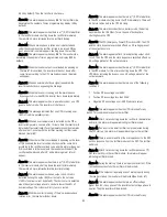
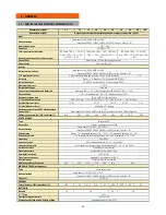
7.3.
SCREEN DESCRIPTION
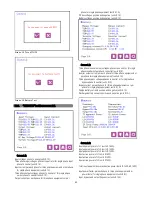
7.3.1. Main level (screen menu 0.0). See Fig. 42
˙
Screen 0.0:
Main presentation screen, with time and date
indication.
Initialization
:
After power on
(Ent)
screen 1.0
(Ent)
screen 4.0
(Ent)
screen 2.0
(Ent)
screen 5.0
(Ent)
screen 3.0
The input/output/battery
voltage and the power flow
(
)(
)
(
)
(
)
DATA(Datalogger)
AIARM(Alarms)
SET
(
Settings
)
CNTL (Control&
Status of the unit)
screen 0.0
MEAS
(
Measures
)
MAIN