2
3
Selection of snatch block
The WLL marked on the block is the maximum load that is allowed to be exerted on the block and it’s connection. Be aware that the Total load on
the block is a result of the rigging method and could be different from the weight being lifted or pulled by the hoisting or hauling system.
It is therefore necessary to determine the total load being imposed on each block in the system to properly determine the block capacity needed.
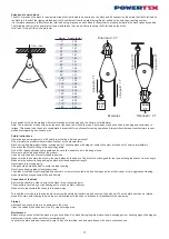
The following chart give the angle factor to be multiplied by the Line pull force to obtain the Total load on the block.
Total load = Line pull force x Angle factor
Line pull force
ANGLE
TOTAL LOAD
Angle
Angle factor
0°
2.00
10°
1.99
20°
1.97
30°
1.93
40°
1.87
45°
1.84
50°
1.81
60°
1.73
70°
1.64
80°
1.53
90°
1.41
100°
1.29
110°
1.15
120°
1.00
130°
0.84
135°
0.76
140°
0.68
150°
0.52
160°
0.35
170°
0.17
180°
0.00
Load
1T
Line pull = 1
T
Load
2T
Line pull = 1T
Line pull = 1T
Total load = 2 T
Examples Total load = 2 T
Line pull = 1
T
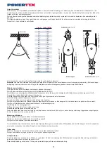
Each snatch block is also marked with recommended wire rope size and the sheave outer diameter.
Note: The redirection motion of the wire rope over the sheave will bend the rope. Some ropes may be sensitive to bending and suspicious to
fatigue. This needs to be taken into consideration, especially for continuously running operations. Always follow the rope manufacturers recom-
mendations regarding min. sheave size.
Safety instructions
Operation and servicing must be left strictly to authorized, trained personnel.
Do not modify the product without written consent by the manufacturer.
Block having illegible product labels, missing parts or showing signs of damage or misfunction must be taken out of service immediately.
Do not use the block for lifting or transporting people.
Do not lift or transport loads over people and do not allow people to be in the danger zone.
Never exceed the load capacity of the product.
Use only with the block’s recommended rope sizes.
Make sure the rope enters the block in the same plane as the sheave. The block is not designed for the rope entering the sheave from an angle.
Make sure the connection supporting the block provides adequate strength.
Never reach into moving parts.
Lifting should be made vertical to avoid the load to swing.
Never leave hanging load without supervision.
The product contains high strength parts and must not come into contact with free hydrogen, acids, alkalis, vapor or very aggressive cleaning
products as they may become brittle and fracture.
Connection of the block
Remove the shackle in order to attach the block to the connection point.
The shackle is secured by a load bearing bolt, nut and a safety cotter pin.
Make sure to reassemble the shackle in the same way.
To insert the wire rope into the snatch block remove the safety hair needle pin and unscrew the quick bolt. The side plate can then be rotated
around the main axle allowing the wire rope to be inserted onto the sheave. Make sure to reassemble the same way.
Storage
After each use check there are no damages to the block.
Clean the snatch block and store it in a dry, clean storage area.
Maintenance
Before every use check that the block is in good condition. Any block having illegible product labels, missing parts or showing signs of damage or
misfunction must be taken out of service immediately.
Lubricate the main axle and the swivel every 14 day of intermittent use and more frequent if used in continuous use.


