PowerTech PL500 User Manual Download Page 9

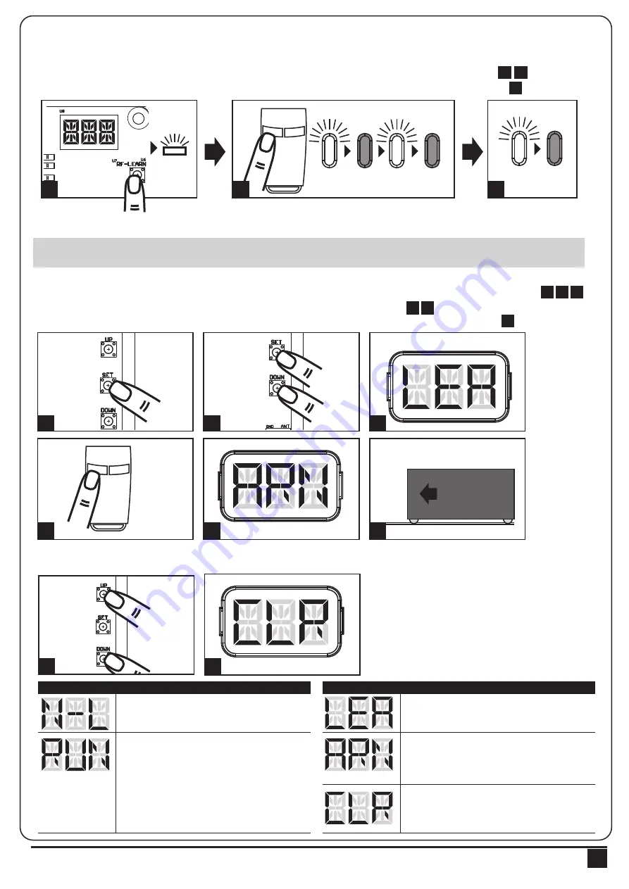
3.2 Transmitter Memorizing and Erasing Process

3.3 System Learning, Reset Process, and LED Display

(1) To Complete the System Learning:

Step1: Press “SET”; then press “SET” + “DOWN” for 3 seconds, and the LED display shows “LEA”
Step2: Press left button (A) on time, the LED display should show “ARN”
Step3: The gate goes to Auto-learning, please wait for the learning process to be completed

(2) To Reset Factory Setting:
Press UP and DOWN for 3 seconds, and the LED display shows “CLR”

(1) Transmitter Memorizing: Press “RF Learn” button for 2 seconds, and the LED3 is on; then press the transmitter  
      left button (A); the LED3 will blink twice and then be off. The transmitter learning is completed.
(2) Erasing Memory: Press "RF Learn" button for 5~6 seconds as LED3 is on, then wait for LED3 off.

LED 3

2 Sec

LED 3

blink twice

LED 3 OFF

1

3

12

13

14

LED1

LED2

LED3

ON

OFF

Press

1~3 Sec

Press

3 Sec

Push

1

2

3

4

5

6

14

LED1
LED2

LED3

ON

OFF

2

3

4

5

6

7

8

9

10

11

12

13

14

LED1
LED2

LED3

ON

OFF

Push

3 seconds

1

2

LED Display 

                      Programmable Functions

LED Display 

                      Programmable Functions

“N-L”: The PL500 system learning is not done.

“LEA”: Enter learning mode and then wait for 
learning instructions. 

“CLR”: Reset Factory Setting. 

“ARN”: The system learning is in progress.

The Auto-learning process of gate moving: 

“Gate open to the end- stop close to the 

end- stop.”

“RUN”: The PL500 system is in normal 

operation To program, press SET button for 3 

seconds, when the LED display change from 

RUN to F1, press UP or DOWN to change 

function settings (F1 to FA). Then press SET 

to enter the sub function within each group, 

press UP or Down to select sub functions 

and press SET for confirmation.

! CAUTION: Before proceeding  to system learning, the transmitter memorizing process has to be completed.

 INSTRUCTIONS PL500 SLIDING GATE OPENER USER MANUAL

7

1

1 2

4 5

6

3

2

3

14

LED1
LED2

LED3

ON

OFF

A

B

A

B

2

Summary of Contents for PL500

Page 1: ...FOR RESIDENTIAL USER MANUAL SLIDING GATE OPENERS PL500 24V DC MOTOR ...

Page 2: ...product has been tasted for CE marking according to the following European Directives 2006 42 EC Machinery Directive Comply with the following Standards EN 301489 1 V1 8 1 2008 EN 301489 3 V1 4 1 2002 EN 300220 1 V2 1 1 2006 EN 300220 2 V2 1 2 2007 EN 60335 1 2002 A11 2004 A1 2004 A12 2006 A2 2006 A13 2008 EN 60335 2 103 2003 EN 62233 2008 EN 12445 2001 EN 12453 2001 And also declare that the mach...

Page 3: ...g Reset Process and LED Display 3 4 Programmable Function Settings 3 5 Testing and Checking 3 6 SW2 SW6 Setting 3 6 1 Recognition of LED 4 Technical Characteriestics 4 1 Technical Data Sheet of Series 4 2 PH 1 Photocell Data Sheet 4 3 PR 1 Transmitter Data Sheet 4 4 PF 1 Flashing Light Data Sheet 4 5 PRB 1 External Receiver Box Data Sheet 5 Additional Information 5 1 Wire Connection of PH 1 Photoc...

Page 4: ... the gates work properly before installing the gate automated system and confirm the gates are appropriate for the application Do not let children operate or play with the gate automated system Do not cross the path of the gate automated system when operating Please keep all the control devices and any other pulse generator away from children to avoid the gate automated system being activated acci...

Page 5: ... photo sensor 4 Flashing light a Operation gear b Limit switch device c 24Vdc motor d Back up batteries Optional e Release device f Control panel g Terminals of devices 2 Installation 3 4 2 3 e f g a b c d 2 2 Description of Device INSTRUCTIONS PL500 SLIDING GATE OPENER USER MANUAL 3 1 ...

Page 6: ...2 3 Dimension of Device 2 4 Installation of Motor Gear and Gear Rack 100 25 50 25 1 2m 4 INSTRUCTIONS PL500 SLIDING GATE OPENER USER MANUAL ...

Page 7: ...ure as below Step1 Push the lid of release chamber and move rightward Step2 Insert the key and turn counterclockwise to unlock the device Step3 Turn counter clockwise of the bar to release the motor To restore the automation simply reverse the above procedure Step1 Step2 Step3 NO OK DX SX INSTRUCTIONS PL500 SLIDING GATE OPENER USER MANUAL 5 ...

Page 8: ... 11 PPB 1 PPB 1 PKS 1 PKS 1 SW1 SW3 SW4 SW5 3 4 PF 1 PF 1 AC INPUT 1 2 3 4 5 6 7 8 9 1 2 3 4 5 6 AC INPUT 1 2 3 4 5 6 7 8 9 10 11 1 2 3 4 5 6 6 INSTRUCTIONS PL500 SLIDING GATE OPENER USER MANUAL LED1 Photocells LED2 Photocells LED3 RF Learn AC INPUT 1 2 3 4 5 6 7 8 9 10 11 12 13 14 1 2 3 4 5 6 ON OFF 1 2 3 4 5 6 7 8 9 10 11 12 13 14 C lo s e S to p G N D P b P h P h 2 P h 1 G N D E X T E X T G N D...

Page 9: ...LED2 LED3 ON OFF Press 1 3 Sec Press 3 Sec Push 1 2 3 4 5 6 1 LED1 LED2 LED3 ON OFF 2 3 4 5 6 7 8 9 10 11 12 13 14 LED1 LED2 LED3 ON OFF Push 3 seconds 1 2 LED Display Programmable Functions LED Display Programmable Functions N L The PL500 system learning is not done LEA Enter learning mode and then wait for learning instructions CLR Reset Factory Setting ARN The system learning is in progress The...

Page 10: ...ght 2 The factory setting is F5 4 3 The motor force value F5 1 2A F5 6 7A F5 2 3A F5 7 8A F5 3 4A F5 8 10A F5 4 5A F5 9 13A F5 5 6A 4 As over current setting 1 The function can adjust the time of opening partially 2 The factory setting is F6 1 3 Press button B on the remote to operate the pedestrian mode 1 The factory setting is F7 0 1 The factory setting is F8 1 1 The factory setting is F9 2 1 Th...

Page 11: ...tomatic closing time Photocell 1 Photocell 2 Stop opening Locks and on release reverses to open Locks and on release continues opening Logic F3 1 The reactions of the photocells when detecting obstacles Gate Status Closed Open Stop during moving Closing Opening Safety Edge Stop opening Stop opening closing Reverses to open for 2 seconds Reverses to close for 2 seconds Photocell 1 No effect Reloads...

Page 12: ...ode Button A left Open Stop Close Stop Button B right Pedestrian Mode Button C up External Device Button D down No Function Button C up Pedestrian Mode Button D down No Function Transmitter SW2 Dip Switch on SW2 Dip Switch off SW6 Dip Switch 4 on Dip Switch 5 off SW6 Dip Switch 4 on Dip Switch 5 off Button C up No Function Button D down External Device Button C up No Function Button D down Pedestr...

Page 13: ...L W H Output 1 Output 2 4 5 PRB 1 External Receiver Box Data Sheet 4 2 PH 2 Photocell Data Sheet 4 Technical Characteristics Detection type Operating distance Response time Input voltage Operating Temperature Protection class Dimension Through beam 25 meters 100ms AC DC 12 24V 20 60 IP54 96mm 45mm 43mm 4 1 Techanical Data Sheet Of Series Worm Gear 5500N 5000N 3800 RPM 60W 24 Vdc 3A 500kg 6 Meters ...

Page 14: ...receiver with the terminals Ph GND and Ph1 on the P600B PCB And use an extra wire to connect terminals 2 and 5 on the receiver as a bridge Detection Method Sensing Range Input Voltage Response Time Emitting Element Operation Indicator Dimensions Output Method Current Consumption Max Water Proof Through Beam 25M AC DC 12 24V 100MS IR LED Red LED RX ON When Beam is Broken Green TX ON 96 45 43mm Rela...

Page 15: ...press and hold Learn Button for 1 second the LED light should be ON If the LED does not respond please check the cable connection again c Press and hold Button C on the remote for 1 second after the LED is ON The remote completed the memorizing process when LED light turns OFF 3 Device Testing Remote Memorization a Orange cable Signal 1 connect to terminal 10 Pb on the control board b Blue cable G...

Page 16: ...ech Automation Inc Output 1 operation LED Light Output 2 operation Single gate operation for Powertech gate openers Dual gate operation for Powertech gate openers 4 Memory Erasing Please refer to figure 5 2 1 5 4 Channel Transmitter Operation Figure 5 2 1 A B C D 34100 095 B ...

Reviews: