background image

4

The Model 20FS staples fl ooring from 5/16” to 1/2” through 
the use of a FLEX foot that can be adjusted to fi t different 
fl ooring profi les.

To use the Model 20FS, simply snug up the fl ooring, pull 
the safety trigger and let the Stapler drive and set the 
staple at the correct 45 degree angle.

The unique body design allows for different grip angles and 
has an adjustable exhaust port to redirect stapler exhaust.  

For a superior pneumatic stapler, look to the company 
that has been the industry’s quality leader, Powernail® 
Company, Inc.

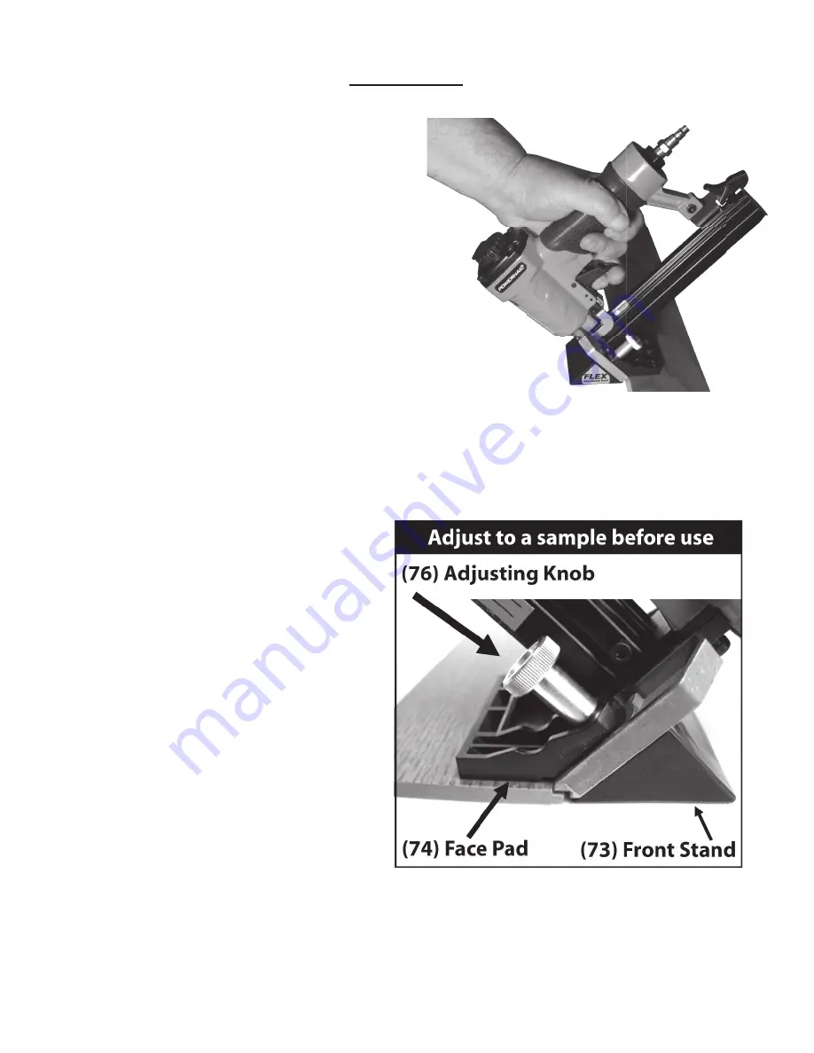
FOOT ADJUSTMENT / STAPLE LOCATION

Figure 1.

Loosen both adjusting knobs (76)

Hold stapler on sample piece of sample 
fl ooring to be installed.

Adjust the face pad (74) so it lays fl at on 
the fi nished surface of the fl ooring (Fig 1).

Lightly snug both adjusting knobs (76).

Push down on front stand (73) so it lays 
fl at on the sub fl oor.

Tighten both adjusting knobs (76).

Test the adjustment by stapling down a 
sample piece of fl oor

Readjust if necessary so that the staple 
insertion point enters the top of the fl ooring 
nail pocket.

OPERATION

Summary of Contents for PowerStapler 20FS

Page 1: ...If you are uncertain about the operation of the stapler call us directly at 1 800 323 1653 for assistance or contact the closest Powernail Dealer for help Please retain this information for future ref...

Page 2: ...must be made no later than fifteen 15 days after the end of the warranty period POWERNAIL will perform all repair or replacements itself or through its authorized contractors POWERNAIL is not respons...

Page 3: ...erations manual Do not use any staples other than Powernail Powerstaples which are specifically designed for use in any Powerstapler Powercleats Staples are available in various lengths Contact your P...

Page 4: ...eumatic stapler look to the company that has been the industry s quality leader Powernail Company Inc FOOT ADJUSTMENT STAPLE LOCATION Figure 1 Loosen both adjusting knobs 76 Hold stapler on sample pie...

Page 5: ...s of air tool oil in the air plug as shown in Figure 3 If you are using an automatic in line oiler check and add oil if necessary 3 Turn your compressor on and set the compressors pressure regulator t...

Page 6: ...and is replaced from the top of the stapler MAINTENANCE 14 13 12 11 10 9 8 7 6 5 4 3 2 1 14a 14b 15 16 17 18 19 22 23 24 25 36 37 38 46 34 35 62 27 33 31 32 31 30 28 39 77 73 71 80 75 72 76 50 51 74...

Page 7: ...tall silver colored safety slide 75 into the silver foot 71 2 Next install the gate 50 and gate plate 72 over the safety slide 75 3 Install the two M4 screws 78 thru the front of the silver foot 71 th...

Page 8: ...10 9 8 7 6 5 4 3 2 1 14a 14b 15 16 17 18 19 22 23 24 25 36 37 38 46 34 35 62 27 33 31 32 31 30 28 39 77 73 71 80 75 72 76 50 51 74 78 43 52 53 43 44 45 56 55 54 1 57 58 59 60 63 64 65 66 36 61 29 79 2...

Page 9: ...Pin n a 36 Locking Washer 09 20FS 5036 37 Spring n a 38 Trigger n a 39 Pin n a 43 Screw n a 44 Movable Magazine Unit n a 45 Stopped Block n a ITEM DESCRIPTION PART 46 Spring Washer n a 50 Gate 09 20F...

Page 10: ...strips into place and ratchets tightly for hands free operation The base of the PowerJack 500 has mounting holes for mid floor use Simply screw nail the PowerJack 500 to your sub floor in front of yo...

Page 11: ...f front plate 3 Inadequate air ow to tool 3 Check hose and compressor tting 4 Worn or dry O ring on piston 4 Replace O ring or lubricate 5 Cylinder cap seal leaking 5 Replace seal 6 Fasteners are jamm...

Page 12: ...POWERNAIL COMPANY INC 1300 Rose Road Lake Zurich IL 60047 US Phone 1 800 323 1653 or 847 847 3000 www powernail com 12...

Reviews: