background image


7

Unpacking 

Open the shipping crate and check for shipping 
damage. Report any damage immediately. Read 
the owner’s manual thoroughly for assembly, 
maintenance and safety instructions. 

Shipping Contents 

Note 1:

 Some parts are inside a box in the cabinet. 

Note 2:

 Models DDS-225 and DDS-237 Drum 

Sanders come from the factory with the first set of 
abrasive strips installed with 80 grit sandpaper on 
the front drum and 100 grit on the rear drum. 

1  dual drum sander 
1 handwheel 
1   handle assembly 
1 handwheel 

post 

2 dust 

ports 

2  open end wrenches (12-14mm and 17-19mm) 
4  hex wrenches (2, 3, 4, and 5mm) 
1 manual 
1 warranty 

card 


Installation and Assembly 

Tools needed 


1  forklift or hoist with straps 


1  14mm open-end wrench (provided) 


1  cross-point screwdriver 


1  flat head screwdriver 


1  set of hex wrenches (provided) 

Remove the screws holding the sander to the 
pallet and use a forklift or hoist to lift the sander off 
the pallet. DO NOT lift directly under the drums or 
rollers, as it may damage them. 

The sander should be placed in a well-lit area with 
a sturdy floor and good ventilation. Leave enough 
space around the machine for loading and off-
loading stock and general maintenance work.  

Exposed metal surfaces, such as the shafts on the 
drums and pressure rollers, have been given a 
protective coating at the factory. This should be 
removed with a soft cloth moistened with kerosene. 
Do not use acetone, gasoline, or lacquer thinner 
for this purpose. Do not use solvents on plastic 
parts, and do not use an abrasive pad because it 
may scratch the surfaces. 


Summary of Contents for DDS-225

Page 1: ... Manual Dual Drum Sander Model DDS 225 DDS 237 WMH TOOL GROUP 2420 Vantage Drive Elgin Illinois 60123 Part No M 0460278 Ph 800 274 6848 Revision D1 04 07 www wmhtoolgroup com Copyright 2007 WMH Tool Group Inc This Manual is Bookmarked ...

Page 2: ...or examination postage prepaid to a location designated by us For the name of the location nearest you please call 1 800 274 6848 You must provide proof of initial purchase date and an explanation of the complaint must accompany the merchandise If our inspection discloses a defect we will repair or replace the product or refund the purchase price at our option We will return the repaired product o...

Page 3: ... Operation 15 Stock Feeding Angle 15 Multiple Piece Sanding Runs 16 Edge Sanding 16 Sanding Imperfect Stock 16 Face Frames Raised Panel Doors 16 Reversing Conveyor Direction 16 Abrasives 16 Maintenance Checklist 18 Troubleshooting 18 Performance Problems 18 Mechanical Electrical Problems 19 Parts DDS 225 Sander 20 Drum Assembly DDS 225 20 Conveyor Assembly DDS 225 22 Motor Cabinet Assembly DDS 225...

Page 4: ...g sawing grinding drilling and other construction activities contain chemicals known to cause cancer birth defects or other reproductive harm Some examples of these chemicals are Lead from lead based paint Crystalline silica from bricks cement and other masonry products Arsenic and chromium from chemically treated lumber Your risk of exposure varies depending on how often you do this type of work ...

Page 5: ...rush Do not have any part of the hands under that part of the board that is over the table when starting a cut the pressure roller will engage the board and force it down against the table causing a pinching action 27 Do not attempt to sand boards with loose knots or with nails or other foreign material on its surface Do not attempt to sand twisted warped bowed or in wind stock unless one edge has...

Page 6: ... Collection Capacity Required CFM 1200 1 200 1 200 Shipping Weight lbs 840 1 142 1 142 Net Weight lbs 730 962 962 Overall Dimensions L x W x H 43 x 44 x 43 60 x 45 x 45 60 x 45 x 45 Main Motor S N 1791290 TEFC 5HP 1Ph 230V 60Hz S N 1791320 TEFC 7 5HP 1Ph 230V 60Hz S N 1791321 TEFC 10HP 3Ph 230 460V prewired 230V 60Hz Conveyor Motor S N 1791290 TEFC 1 4HP 1Ph 230V 60Hz S N 1791320 TEFC 1 4HP 1Ph 23...

Page 7: ...hoist with straps 1 14mm open end wrench provided 1 cross point screwdriver 1 flat head screwdriver 1 set of hex wrenches provided Remove the screws holding the sander to the pallet and use a forklift or hoist to lift the sander off the pallet DO NOT lift directly under the drums or rollers as it may damage them The sander should be placed in a well lit area with a sturdy floor and good ventilatio...

Page 8: ...lectrical connections must be made by a qualified electrician in compliance with all relevant codes The machine must be properly grounded to help prevent electrical shock and possible fatal injury A power plug is not provided with the DDS 225 or DDS 237 Dual Drum Sander You may either connect the proper UL CSA listed plug or hardwire the machine directly to your electrical panel provided there is ...

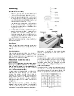
Page 9: ... the starting edge of your next strip 4 Mark and cut a taper at the right end of the abrasive strip Fig 4 Because the tapered end should use all of the recess at the right side of the drum its end must be trimmed back leaving an edge of about 1 2 inch as shown Now trim the left side of the abrasive paper in a similar manner Fig 5 Note An alternate method of tapering the ends of the abrasive strip ...

Page 10: ...piece must vary To achieve this the back drum which should always have the finer grit has been designed for easy adjustment 1 Loosen the locking levers Fig 8 on both sides of the machine by rotating them counter clockwise 2 Rotate the adjustment knob to the desired measurement using the red triangular indicator at the base of the dial A label is affixed below the locking lever showing the proper s...

Page 11: ...piece from passing through the machine and may cause the conveyor belt to stop Table Height Rotate the handwheel until the depth gauge Fig 11 reads the appropriate depth One revolu tion of the handwheel moves the table approxim ately 1 16 A limit plate Fig 11 is mounted to the front of the sander If the table has been set too high the workpiece will contact this plate and a limit switch will shut ...

Page 12: ...usting the table height becomes difficult or if excessive clearance forms between the lead screws and bushings adjustment may be required as described below Symptoms Table wobble is noted Difficulty is noted in table height adjustment Corrective action 1 Determine the corner s requiring adjustment 2 Use a 1 8 hex wrench to loosen the setscrew A Fig 19 between 1 4 and 1 2 turn To remove excessive c...

Page 13: ...s drifting tighten the knob 1 4 turn Fig 15 to shift the belt to the opposite direction 2 On the side of the conveyor away from which the belt is drifting loosen the knob 3 After adjusting each take up knob allow time for the belt to react to the adjustments before proceeding further Continue this adjustment until the conveyor belt is tracking properly in the center of the table Try to avoid over ...

Page 14: ... in the belts and remove the two belts from around the motor pulley Belts should always be replaced as a matched set Remove the four bolts holding the front drum to the sides of the cabinet and lift the front drum out of the machine On the rear drum loosen the two bolts at the right side of the drum but do not remove them Completely remove the two bolts that hold the left side of the drum to the c...

Page 15: ...st collector system 5 Feed stock through unit Determining depth of cut is one of the most important procedures for the sander It may take some experimentation to determine the proper depth of cut given the variables of abrasive grit type of wood and feed rate For best results use scrap wood to practice sanding and to develop skill and familiarity with the machine before doing finish work A good ru...

Page 16: ...pport such stock as it is being sanded to keep it from slipping or tipping Use extra roller stands help from another person or hand pressure on the stock to minimize potentially hazardous situations Figure 20 Face Frames Raised Panel Doors It is important to have the proper abrasive contact when doing this type of sanding If the machine is set to take an excessive depth of cut the result can be a ...

Page 17: ...commercially available cleaning sticks following the manufacturer s directions When cleaning also brush the stick crumbs from the drum while it is still rotating CAUTION Wear tight fitting clothes and eye protection during this procedure stay alert to prevent injury Cloth backed abrasives can be cleaned by soaking in paint thinner or mineral spirits for 20 minutes to 1 hour then using a brush to r...

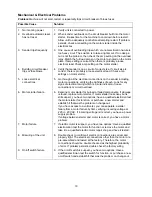
Page 18: ...erent stock Work burns Wrong grit Use coarser grit for stock removal Abrasive belt burns clogs quickly Biting too deep Adjust for slight sanding action and make repeated passes Excessive abrasive belt replacement Biting too deep Reduce cut and make multiple passes Sanding marks on workpiece Abrasive belt too coarse for finish required Sanding across the grain Use proper grit for finish sanding Whe...

Page 19: ...nections on the sander including motor connections verifying the tightness of each Look for any signs of electrical arcing which is a sure indicator of loose connections or circuit overload 6 Examine motor starter for burned or failed components If damage is found replace motor starter If motor starter looks okay but is still suspect you have two options have a qualified electrician test the motor...

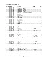
Page 20: ...Washer 3 8 16 25 TS 1550071 Flat Washer M10 4 26 TS 0207061 Socket Head Cap Screw 1 4 20 x 1 4 27 TS 0270091 Socket Set Screw 5 16 18 x 1 4 28 TS 0060021 Hex Cap Screw 3 8 16 x 5 8 4 29 TS 0060051 Hex Cap Screw 3 8 16 x 1 2 30 TS 0208021 Socket Head Cap Screw 5 16 18 x 1 2 4 31 TS 0270051 Socket Set Screw 5 16 18 x 1 2 2 32 DDS225 132 Spring 2 33 DDS225 133 Steel Ball 5mm 2 34 TS 0267021 Socket Se...

Page 21: ...rum Assembly DDS 225 Index No Part No Description Size Qty 54 DDS225 154 Front Drum 1 55 TS 1521021 Socket Set Screw M4 x 6 4 56 DDS225 156 Roll Pin 2 x 8mm 2 57 Abrasive see Optional Accessories on page 38 ...

Page 22: ...st Bearing 4 27 DDS225 227 Roll Pin 6 x 25mm 1 28 DDS225 228 Chain 1 29 TS 081F022 Phillips Pan Head Machine Screw 1 4 20 x 3 8 1 30 TS 0050011 Hex Cap Screw 1 4 20 x 1 2 8 31 TS 0207111 Socket Head Cap Screw 1 4 20 x 2 1 4 16 32 TS 0720071 Lock Washer 1 4 16 33 TS 0561082 Hex Nut 3 4 16UNF 8 34 DDS225 234 Key 5 x 5 x 18mm 4 35 TS 0208041 Socket Head Cap Screw 5 16 18 x 3 4 16 36 TS 0720081 Lock W...

Page 23: ... No Part No Description Size Qty 56 TS 081C022 Screw 10 24 x 3 8 8 57 DDS237 260 Boot 4 58 DDS237 258 Special Washer 4 59 TS 0208021 Socket Head Cap Screw 5 16 18 x 1 2 8 60 DDS225 260 Nylon Washer 4 61 TS 0267051 Set Screw 1 4 20x1 2 4 ...

Page 24: ... Cap Screw 3 8 16 x 3 4 6 29 TS 0720091 Lock Washer 3 8 10 30 TS 1550071 Flat Washer M10 4 31 TS 0050051 Hex Cap Screw 1 4 20 x 1 1 32 TS 0207021 Socket Head Cap Screw 1 4 20 x 1 2 2 33 TS 0720071 Lock Washer 1 4 20 34 TS 0050061 Hex Cap Screw 1 4 20 x 1 1 4 1 35 TS 0640071 Hex Nylon Lock Nut 1 4 20NC 2 36 DDS225 336 Hex Head Screw 1 4 20 X 3 8 6 37 TS 0680021 Flat Washer 1 4 10 38 TS 0050011 Hex ...

Page 25: ...90111 Hex Cap Screw M8 x 60 2 72 DDS225 372 Spring 2 73 TS 1540061 Hex Nut M8 2 74 TS 081F022 Phillips Pan Head Machine Screw 1 4 20 x 3 8 4 75 DDS225 375 Screw 3 16 24 x 1 1 4 2 76 DDS225 376 Limit Switch 1 77 DDS225 377 Cord Holder 2 78 DDS225 378 Switch Cord Mag Switch to Main Motor 1 79 DDS225 379 Switch Cord Reverse Switch to Conveyor Motor 1 80 TS 2284082 Phillips Pan Head Machine Screw M4 x...

Page 26: ...26 Motor Cabinet Assembly DDS 225 ...

Page 27: ...Shaft 1 17 DDS225 417 Cover 1 18 TS 1503041 Socket Head Cap Screw M6 x 16 9 19 DDS225 419 Key 5 x 5 x 30 1 20 DDS225 420 Collar 1 21 DDS225 421 Oil Plug 1 22 DDS225 422 Handle 1 23 BB 6006VV Ball Bearing 1 24 DDS225 424 C Ring 1 25 DDS225 425 Gear 64T 1 26 DDS225 426 Key 8 x 8 x 15 1 27 DDS225 427 Block 1 28 DDS225 428 Pin 1 29 DDS225 429 Gear 77T 1 30 DDS225 430 Key 6 x 6 x 50 1 31 DDS225 431 Cab...

Page 28: ...28 Gearbox Assembly DDS 225 Drum ...

Page 29: ...rew 3 8 16 x 1 3 4 4 24 TS 0720091 Lock Washer 3 8 8 25 TS 1550071 Flat Washer M10 4 26 TS 0207061 Socket Head Cap Screw 1 4 20 x 1 4 27 TS 0270051 Socket Set Screw 5 16 18 x 1 2 4 29 TS 0060051 Hex Cap Screw 3 8 16 x 1 2 30 TS 0208021 Socket Head Cap Screw 5 16 18 x 1 2 4 31 TS 0270051 Socket Set Screw 5 16 18 x 1 2 2 32 DDS225 132 Spring 2 33 DDS225 133 Steel Ball 1 4 2 34 TS 0267021 Socket Set ...

Page 30: ...um Assembly DDS 237 Index No Part No Description Size Qty 55 TS 1521041 Socket Set Screw M4 x 10 4 56 DDS225 156 Roll Pin 2 x 8mm 2 57 TS 0720091 Lock Washer 3 8 8 58 TS 0100041 Hex Cap Screw 1 2 13x 1 1 4 4 ...

Page 31: ... Bearing 4 27 DDS225 227 Roll Pin 6 x 25mm 1 28 DDS237 228 Chain 1 29 TS 0813022 Round Head Machine Screw 1 4 20 x 3 8 1 30 TS 0050011 Hex Cap Screw 1 4 20 x 1 2 8 31 TS 0207111 Socket Head Cap Screw 1 4 20 x 2 1 4 16 32 TS 0720071 Lock Washer 1 4 16 33 TS 0561082 Hex Nut 3 4 16UNF 8 34 DDS225 234 Key 5 x 5 x 18mm 4 35 TS 0208041 Socket Head Cap Screw 5 16 18 x 3 4 16 36 TS 0720081 Lock Washer 5 1...

Page 32: ...e Qty 58 DDS237 258 Special Washer 4 59 DDS237 259 Upper Bracket 4 60 DDS237 260 Boot 4 61 TS 081C022 Screw 10 24 x 3 8 8 62 TS 0680021 Flat Washer 1 4 8 63 DDS225 336 Hex Head Screw 1 4 20 x 3 8 8 64 DDS225 260 Nylon Washer 4 65 TS 0267051 Set Screw 1 4 20x1 2 4 ...

Page 33: ...Block 2 10 DDS225 310 Cylinder 2 11 DDS237 311 Flow Deflector 1 12 DDS237 312 Top Cover 1 13 DDS225 313 Dust Chute 2 14 DDS225 314 Roller Holder 1 15 DDS225 315 Idle Roller 1 16 DDS237 316 Switch Bracket 1 17 DDS225 317 Direction Label 1 18 DDS225 318 Scale 1 19 DDS225 319 Spacer 1 20 DDS225 320 Door Latch 3 21 DDS225 321 Handle 1 22 DDS237 322 Magnetic Switch for 7 1 2HP 1Ph 230V 1 DDS237 322C Co...

Page 34: ...t Cover 1 56 TS 0680011 Flat Washer 3 16 26 57 DDS225 WL Warning Label 1 58 TS 081C022 Screw 10 24 x 3 8 14 59 DDS237 359 Rear Cover 1 60 DDS225 360 Self Tapping Screw 10 x 1 2 2 61 TS 069204 Flat Washer SAE 10 2 62 DDS225 362 Lock Piece 2 63 DDS225 363 Plastic Nut 2 64 DDS225 364 Lock Housing 2 65 DDS225 365 Lock Knob 2 66 TS 0207021 Socket Head Cap Screw 1 4 20 x 1 2 4 67 TS 0720071 Lock Washer ...

Page 35: ...35 Motor and Cabinet Assembly DDS 237 Index No Part No Description Size Qty 86 DDS237 386 I D Label not shown 1 87 TS 2361101 Lock Washer M10 1 88 DDS237 388 Pad 4 89 DDS237 389 Strain Relief 2 ...

Page 36: ...0 1 20 DDS225 420 Collar 1 21 DDS225 421 Oil Plug 1 22 DDS225 422 Handle 1 23 BB 6006VV Ball Bearing 1 24 DDS225 424 C Ring 1 25 DDS225 425 Gear 64T 1 26 DDS225 426 Key 8 x 8 x 15 1 27 DDS225 427 Block 1 29 DDS225 429 Gear 77T 1 30 DDS225 430 Key 6 x 6 x 50 1 31 DDS225 431 Cable for 1 4HP 1Ph 230V 1 DDS237 431 Cable for 1 4HP 3Ph 230 460V 1 32 DDS225 432 Motor 1 4HP 1Ph 230V 1 DDS225 432MF Motor F...

Page 37: ...37 Gearbox Assembly DDS 237 ...

Page 38: ...nsioning boards truing warped boards 60 9080 80 Grit Sandpaper surfacing light dimensioning removing planer ripples 60 9100 100 Grit Sandpaper light surfacing removing planer ripples 60 9120 120 Grit Sandpaper light surfacing minimal stock removal 60 9150 150 Grit Sandpaper finish sanding minimal stock removal 60 9180 180 Grit Sandpaper finish sanding only not for stock removal 60 9220 220 Grit Sa...

Page 39: ...39 Wiring Diagram DDS 225 Sander ...

Page 40: ...BLACK BLACK WHITE GREEN BLACK WHITE 98 96 95 97 250VAC 250MFD 450VAC 50UF GREEN BLACK WHITE GREEN BLACK WHITE WHITE BLACK GREEN WHITE YELLOW S 6 R FRONT U BACK BLACK RED V 5 350VAC 10UF 6 4 5 1 BLACK RED WHITE YELLOW GREEN WHITE BLACK GREEN GREEN BLACK WHITE REVERSING SWITCH 250VAC 250MFD LIMITED SWITCH RED RED ...

Page 41: ...N WHITE RED BLACK V W2 Y1 W U2 Z1 U V2 X1 U1 V1 W1 5L3 A1 3L2 13NO 1L2 17 18 2T1 4T2 6T3 14NO 2T1 4T2 6T3 A2 GROUND GREEN WHITE BLACK BLACK WHITE GREEN BLACK WHITE 98 96 95 97 GREEN BLACK WHITE GREEN BLACK WHITE WHITE BLACK GREEN WHITE L1 FRONT BACK BLACK RED V WHITE BLACK GREEN GREEN BLACK WHITE REVERSING SWITCH ...

Page 42: ... V1 W1 W5 V5 U5 U2 V2 W2 U W L2 L3 RED GREEN WHITE RED BLACK V V2 W1 W W2 U1 U U2 V1 Z1 X1 Y1 2T1 4T2 6T3 A2 GROUND GREEN WHITE BLACK BLACK WHITE GREEN BLACK WHITE 98 96 95 97 GREEN BLACK WHITE GREEN BLACK WHITE WHITE BLACK GREEN WHITE L1 FRONT BACK BLACK RED V WHITE BLACK GREEN GREEN BLACK WHITE REVERSING SWITCH ...

Page 43: ...43 Notes ...

Page 44: ...44 WMH Tool Group 2420 Vantage Drive Elgin Illinois 60124 Phone 800 274 6848 www wmhtoolgroup com ...

Reviews: