


28
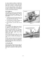
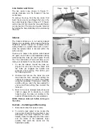
Indexer Positions
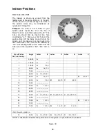
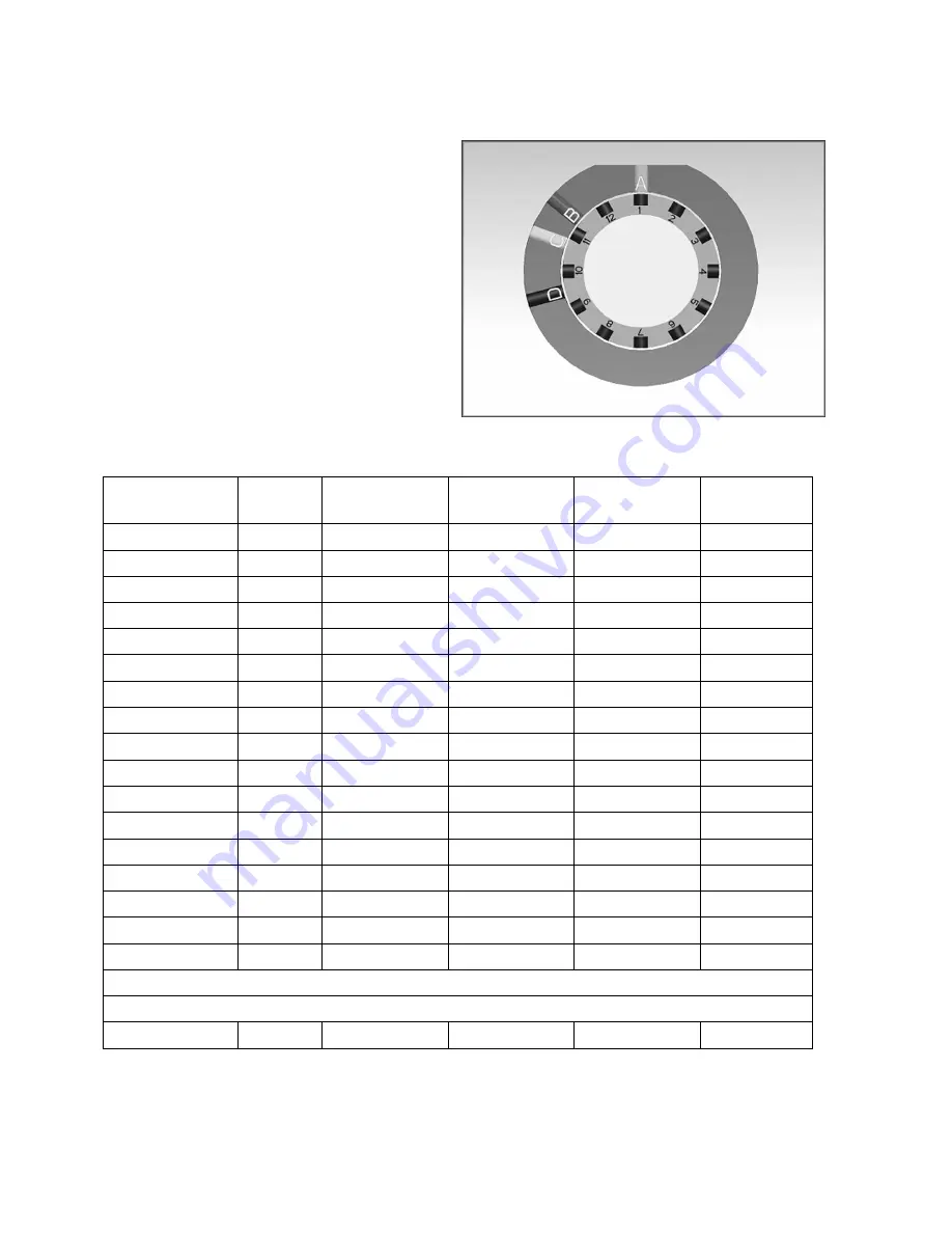
How to use the chart
The indexer is shown as viewed from the
tailstock end of the Lathe. Points A, B, C and D
are the holes in the head casting. The holes in
the spindle collar may be considered as
numbered 1 through 12.
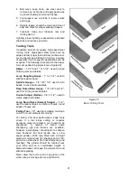
Example: You wish to rout 9 flutes on your
spindle blank. Locate the “9” in the “No. of
Flutes” column; each flute angle will be 40°. The
index pin should first be inserted into hole
combination “A-1”. Make your first flute at this
position. Back off the index pin and rotate the
spindle until the index pin can be inserted into
hole combination “A-5”; this will be followed by
“A-9”. Succeeding flutes will be made with the
index pin in the B position: “B-2”, “B-6” and so
on.
No. of Flutes
360° divided by...
Angle
Letter #
Letter #
Letter #
Letter #
1 360.00
A 1
2 180.00
A 1,7
3 120.00
A 1,5,9
4 90.00
A 1,4,7,10
5 72.00
-----------------------
6 60.00
A 1,3,5,7,9,11
8 45.00
A 1,4,7,10
D 2,5,8,11
9 40.00
A 1,5,9
B 2,6,10
C 4,8,12
10 36.00
-----------------------
12 30.00
A 1 to 12
15 24.00
-----------------------
16 22.50
-----------------------
18 20.00
A 1,3,5,7,9,11
B 2,4,6,8,10,12
C 2,4,6,8,10,12
20 18.00
-----------------------
24 15.00
A 1 to 12
D 1 to 12
30 12.00
-----------------------
36 10.00
A 1 to 12
B 1 to 12
C 1 to 12
other interesting patterns....
18 20.00
A 1,3,5,7,9,11
B 1,3,5,7,9,11
C 1,3,5,7,9,11
NOTE: A dashed line indicates that particular set of angles is not possible with the indexer.
Figure 39
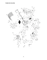
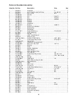
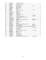
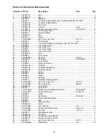
Summary of Contents for 3520B
Page 31: ...31 Headstock Assembly ...
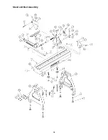
Page 34: ...34 Stand and Bed Assembly ...
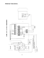
Page 40: ...40 Electrical Connections ...
Page 42: ...42 NOTES ...
Page 43: ...43 ...