background image

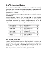
6. UPS Operating Modes


On  the LCD  panel of the  UPS,  a code is  displayed to indicate the operating 

mode of the UPS. The codes displayed can also indicate a fault or a warning. 

The  table  below  shows  the  meanings  of  the  different  codes  that  can  be 

displayed on the UPS LCD. 

Note that, at  any  time instant,  only  one operating mode  or a fault mode can 

be represented. 

If  several  warnings  exist  in  a  given  operating  mode,  the  codes  of  these 

warnings and the code that indicates the operating mode are shown cyclically.  

Once  a  fault  comes  forth,  the  codes  of  all  existing  warnings  will  not  be 

displayed and only the code of the existing fault will be displayed.


Operating mode 

code 

    Operating mode 

code 

No-output mode 

00 

    Overload fault 

07 

     Bypass mode 

01 

    Over temperature fault 

08 

     Line mode 

02 

    Site fail warning 

09 

     Battery mode 

03 

    Fan fail warning 

10 

     Battery test mode 

04 

    Battery over-charge warning 

11 

     Bus fault 

05 

    Battery weak warning 

12 

     Inverter fault 

06 

    Charger fail warning 

13 


6.1 Line Mode of Operation 

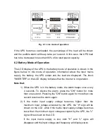
The  LCD  display  of  the  UPS  in  the  line  mode  of  operation  is  shown  in  the 

following figure. In this mode of operation, information about the input mains 

supply,  the  battery,  the  UPS  output  and  the  load  are  displayed.  The  block 

"INVERTER" on the LCD display indicates that the inverter is in operation. 

Note that the code that indicates this mode of operation is "02".


Summary of Contents for 1KT

Page 1: ...USER MANUAL LCD 1 3Kva models Uninterruptible Power Supply...

Page 2: ...ng Modes 6 1 Line Mode of Operation 6 2 Battery Mode of Operation 6 3 Bypass Mode of Operation 6 4 No Output Mode of Operation 6 5 Abnormal Mode of Operation 7 Setting the UPS Parameters 8 Troubleshoo...

Page 3: ...near heat Do not block off the ventilation openings of the UPS cabinet 1 3 Installation Do not connect appliances or items of equipment which may overload the UPS such as laser printers to the output...

Page 4: ...he UPS is not connected to an AC supply For complete disconnection of the UPS system first press the OFF button for more than one second then disconnect the mains power supply cable Ensure that no flu...

Page 5: ...an present a risk of electrical shock and have high short circuit current The following precautions and any others necessary measures should be observed Remove watches rings or other metal objects Use...

Page 6: ...should be familiar with these symbols and understand their meanings Symbol Explanation Caution Special Attention is Required Risk of Electric Shock Turning ON the UPS Turning OFF the UPS Idle or Shutd...

Page 7: ...he inverter in its turn generates a sinusoidal AC voltage which permanently supplies the loads with uninterrupted clean and sine wave voltage Computers and peripherals are thus powered entirely by the...

Page 8: ...OFF button the inverter turns off and if the mains power supply is normal the UPS system switches to Standby or Bypass mode The UPS output sockets will be supplied via the bypass circuit Select Button...

Page 9: ...specified range the UPS will work in the battery mode Indicates that the input supply voltage is lower than the specified range the UPS will work in the battery mode Output Information Displays the va...

Page 10: ...de and the warning codes of the UPS For the meaning of these codes refer to page 13 Inverter operating Information Indicates that the inverter is running Bypass operating Information Indicates that th...

Page 11: ...eater than the UPS input current over 10A for 1KT XL and 2KT models and over 16A for 3KTand 3KT XL models 5 2 2 UPS Output Connection The outputs of the UPS1KT and 1KT XL are socket type only Simply p...

Page 12: ...r 2KS 3K and 3KT XL models 5 2 3 Computer Connection Connect your computer to the UPS socket outlet using the above diagram 5 3 Battery Charging To fully charge the batteries of the UPS keep the UPS c...

Page 13: ...st the UPS press the ON button of the UPS or disconnect the input mains supply 5 6 Turning Off the UPS 5 6 1 In Line Mode Press the OFF button continuously for more than one second At the beginning th...

Page 14: ...o the external battery cabinet 3 Do not connect any load to the UPS output Connect the input power cable of the UPS to the input mains supply to operate the UPS in the utility power mode 4 Connect the...

Page 15: ...be displayed and only the code of the existing fault will be displayed Operating mode code Operating mode code No output mode 00 Overload fault 07 Bypass mode 01 Over temperature fault 08 Line mode 02...

Page 16: ...ER on the LCD display indicates that the inverter is in operation Note that 1 When the UPS is in the battery mode the alarm beeps once every 4 seconds To silence the alarm press the ON button for more...

Page 17: ...at indicates the battery test mode is 04 6 3 Bypass Mode of Operation The LCD display of the UPS in the bypass mode of operation is shown in the figure below In this mode of operation information abou...

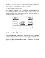
Page 18: ...ins supply the battery the UPS output and the load are displayed The code that indicates this mode of operation is 00 Fig 6 4 No output mode of operation 6 5 Abnormal Mode of Operation This mode of op...

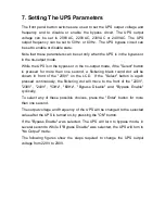
Page 19: ...an one second a flickering black round dot will be shown in front of the 208V on the LCD If the Select button is again pressed continuously the flickering dot will move to the front of the 220V 230V 2...

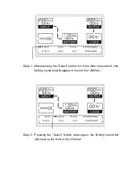
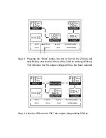
Page 20: ...ressing the Select button for more than one second one flicking round dot will appear in front of the 208Vac Step 2 Pressing the Select button twice again the flicking round dot will move to the front...

Page 21: ...he dot in front of the 230Vac will stop flicking and the dot in front of the 240Vac will begin flicking This indicates that the output voltage 230Vac has been selected Step 4 After the UPS turns to ON...

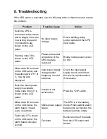
Page 22: ...hown on the LCD panel and the warning word H or L may be also displayed Input power supply voltage and or frequency is out of tolerance Check the input power supply source and inform the service repre...

Page 23: ...backup time Contact the service representative Warning code 13 is shown on the LCD panel the alarm beeps once per second Charger or Battery faulty Contact the service representative Warning code 10 is...

Page 24: ...eeded the batteries have to be replaced For battery replacement contact your dealer 9 2 Storage If the UPS is stored in a temperate climatic environment recharge the battery every three months by conn...

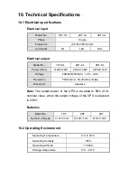
Page 25: ...0 240 2 VAC Frequency 50 60 0 2 Hz Battery mode Waveform sinewave Note The output power of the UPS is de rated to 90 of its nominal value when the output voltage of the UPS is adjusted to 208V Batteri...

Page 26: ...34 5 2KT XL 192X460X340 15 3KT 192X460X340 35 5 3KT XL 192X460X340 16 10 5 Safety and EMC Standards GB4943 EN62040 1 1 safety Conducted Emission GB7260 2 EN62040 2 Class B Radiated Emission GB7260 2 E...

Page 27: ...ional accessory for AS400 communication protocol This interface provides true relay contact output to peripheral devices The following is the pin assignment and description of DB 9 connector in AS400...

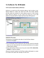
Page 28: ...e these UPS systems W Installation Procedure The following is the installation procedure for the WinPower software 1 Connect to the website http www ups software download com winpower htm 2 From the d...

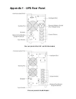
Page 29: ...Appendix 1 UPS Rear Panel The rear panel of the 1KT and 1KT XL models The rear panel of the 2KTmodel...

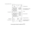
Page 30: ...The rear panel of the 3KT and 3KT XL models...

Reviews: