


1. Guide the blue and black hydraulic tubing through the black
mesh tubing cover
WARNING:
Keep debris out of the hydraulic tubing. Use the
red end caps provided at all times while routing the
hydraulic tubing throughout the boat. Debris in the
tubing will cause damage to the HPU.
2. The hydraulic tubing may be routed either over the transom
or through the transom. (
FIG. 5-8
). If the hydraulic tubing is
not being installed through the transom, route the tubing to
the HPU and proceed to Step 4 below.
IMPORTANT:
Be sure to allow an adequate amount of slack in
the hydraulic tubing between the stern bracket and
the point that the tubing enters the vessel. This will
provide for full up and down operation.
3. Mark and drill holes in the transom with a 11/32” drill bit
above the water line spaced 1/4” apart. Insert the (2) thru-hull
bushings
K
, and route the tubing to the HPU. (
FIG. 9 & 10
)
4. Trim the excess tubing with a razor. All cuts made in the tubing
must be as straight as possible to ensure that the compression
fittings do not leak.
5. Remove the blue and black dust caps from the hydraulic
compression fittings on the HPU.
6. Remove the
“Insert Blue Tubing Here tag”
and push the
blue tubing into compression fitting. Hold the blue tubing fully
inserted into the compression fitting base and begin threading
the compression fitting nut onto the base. Repeat this step for
the black tubing. (
FIG. 11 & 12
)
NOTE:
The tubing needs to pass through the ferrule far enough
such that there is approximately a 1/2” length of tubing
exposed. (
FIG. 11
)
7. Tighten both compression fitting nuts with a 9/16” wrench
while holding their respective bases with a 1/2” wrench.
(
FIG. 13
)
WARNING:
The nuts must be tightened down far enough so that
none of the compression fitting’s threads are visible, failure to
tighten completely may cause hydraulic failure. (
FIG. 14
)
Figure 5 Blade
Figure 7 Blade
Figure 9
Figure 10
Figure 11
Figure 13
Figure 14
Figure 12
Figure 6 Pro II & Sportsman
Figure 8 Pro II & Sportsman
over transom
through transom
through transom
over transom
STEP
5
Installing The Hydraulic Tubing
K
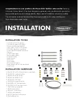
www.power-pole.com
Summary of Contents for Blade
Page 1: ...INSTALLATION MANUAL ...


