2.
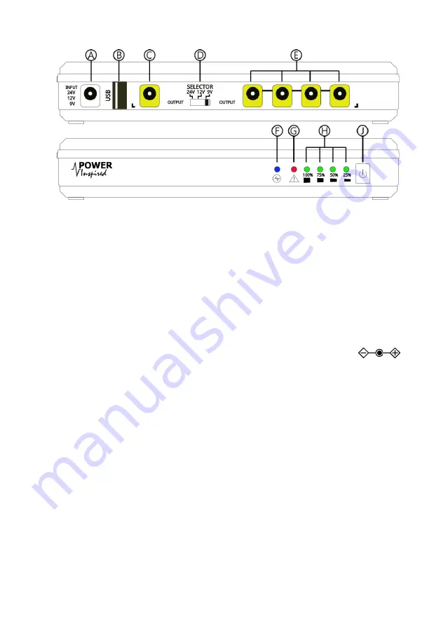
Layout
Ⓐ
DC Input Socket
Ⓓ
Voltage Selector Switch
Ⓖ
Warning / Fault
Ⓑ
USB Output
Ⓔ
Secondary DC Outputs
Ⓗ
Battery Status Indicators
Ⓒ
Primary DC Output
Ⓕ
Set Voltage Indicator
Ⓙ
On/Off Switch
3.
Installation & Operation
▪
The iPower-DC
2
connects between the equipment DC supply and the equipment
itself.
▪
Choose a suitable location out of direct sunlight and sources of heat with suitable
access to the DC power supply and the connected equipment.
▪
Set the Voltage Selector Switch
Ⓓ
to match the required voltage.
▪
Note the polarity of both input and output DC jacks is centre pin positive
▪
Plug in the DC adapter or DC source into input socket
Ⓐ
and apply power.
▪
The iPower-DC
2
will automatically start up.
▪
Ensure the voltage indicator LED
Ⓕ
is indicating the correct voltage:
24V: RED
12V: BLUE
9V: PURPLE (RED & BLUE)
▪
If the Voltage Indicator LED
Ⓕ
is flashing and the Fault LED
Ⓖ
is illuminated the
input voltage does not match the voltage selector switch
Ⓓ
setting. Switch the unit
OFF by disconnecting the input DC power source from
Ⓐ
and pressing and holding
the Power Off button
Ⓙ
until all the LEDs extinguish (around 3 seconds). Set the
selection switch to the correct voltage and repeat.
▪
Plug the equipment into the USB
Ⓑ
and/or DC output jacks
Ⓒ
Ⓔ
as required using
the DC male cables provided. For best performance the primary DC equipment
should be connected to port
Ⓒ
. You can use USB and DC jack outlets at the same
time provided the unit rating is not exceeded.
3.1.
Battery Operation
▪
The iPower-DC
2
will immediately transfer to battery power if the input DC voltage is
lost. There is no loss of power to connected equipment.


