8
Power-Flo Pumps & Systems • 877-24PUMPS • www.powerflopumps.com
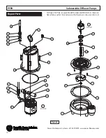
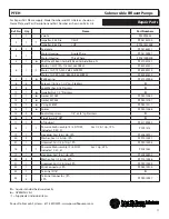
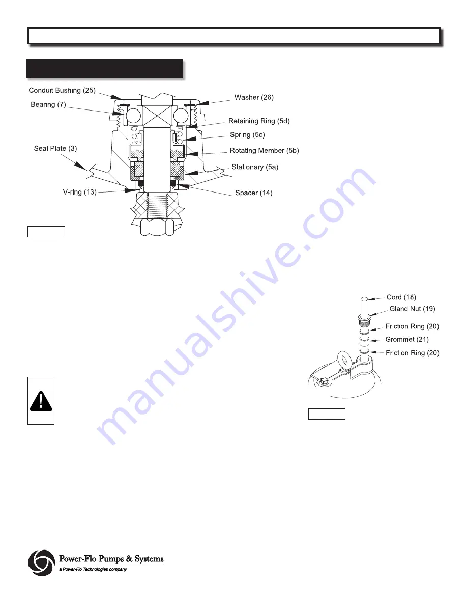
If replacing the seal, remove stationary
(5a) from seal plate (3) by prying out with
screw driver.
BEARING -
Examine bearing (7) and
replace if worn. Remove bearing (7) from
shaft using a wheel puller, if replacement
is required. The washer bushing (26)
and conduit bushing (25) can now be
removed.
REASSEMBLY
IMPORTANT! - All parts must be
clean before reassembly.
Handle seal parts with extreme
care. DO NOT damage lapped
surfaces.
To reassemble
-
clean seal cavity in seal
plate (3) and oil. Press seal’s (5) stationary
member (5a) firmly into seal plate (3),
using a seal tool or pipe. Nothing should
come in contact with the seal face except
the seal tool. Be sure the stationary is in
straight. Lightly oil
(Do not use grease)
shaft and inner surface of bellows.
Slide retaining ring (5d) and spring (5c)
over shaft and let rest on bearing. Lightly
oil
(Do not use grease)
shaft, bullet
and inner srface of bellows on rotating
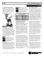
member (5b). See Figure 3. With lapped
surface of rotating member (5b) facing
outward, slide over seal tool and unto
shaft, making sure spring (5c) is seated in
retaining ring (5d) and spring (5c) is lined
up on rotating member (5b) and not
cocked or resting on bellows tail.
Place conduit bushing (25) and washer
(26) onto shaft. Slide rotor/shaft (6) with
bearing (7) and seal (5) into seal plate
(3) until bearing (7) seats into seal plate.
Locate washer (26) into place on bearing
and tighten conduit bushing (25) onto
seal plate (3). Place stator (6) over rotor
(6), lining up motor bolts with holes in
seal plate (3). Position capacitor (29) on
motor with clamp (30) and reconnect
capacitor leads. Torque motor bolts to
17 in-lbs. Set square ring (11) in grove on
seal plate (3).
Lower motor housing (4) down onto
seal plate (3) while aligning holes and
stringing motor leads through the cord
entry bore. Place socket head screws (15)
through seal plate (3) into housing (4)
and torque to 60 in-lbs. Reconnect motor
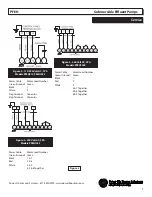
leads, as shown in Figure 5.
Power Cable Connection
Check power cord (18) for cracks or
damage and replace if required. Insert
one washer (20), grommet (21), washer
(20) into motor housing (4). Apply pipe
sealant to gland nut (19) and screw into
motor housing (4). Torque gland nut to
(19) to 15 ft. lbs. to prevent water leakage
(See Figure 4). Refill the cooling oil and
replace pipe plug (16).
Insert spacer (14) and v-ring (13) into seal
plate (3) and reassemble remaining parts
per “Impeller, V-ring and Volute” section on
page 7.
Service
PFEH
Submersible Effluent Pumps
Figure 3
Figure 4

