background image

10  

For technical questions call 1-800-665-8685

V 3.05 

8474116

20 Gallon Pressure Abrasive Blaster

CAUTION! Make sure that the tank has been depressurized before attempting to remove the tank filler  

cap (12).

WEAR CONDITIONS

This is usually noted when an excessive amount of dust appears while blasting. Dust will occur if:

1.  The abrasive blasting media is worn out if it has lost its granular or spherical appearance or has a lot of 

debris mixed in from the parts being blasted.  Replace the abrasive blasting media. This is usually noticed 

when the abrasive media that exits the nozzle resembles more of a cloud than a stream.

2.  The deadman valve parts may wear out. This is usually evident when the blast pattern is too wide and 

ineffective; simply replace the nozzle or orifice.

LUBRICATION

Do not use lubricants or air tool oil on the unit. The oil will contaminate the abrasive media, clogging the tool and 

reducing the effectiveness of the abrasive.

STORAGE

With a dry, clean cloth or brush, remove any contaminants from the unit and the deadman valve before placing the 

unit in storage.

DISPOSING OF THE TOOL

1.  If your tool has become damaged beyond repair, do not throw it out. Take it to the appropriate  

recycling facility.

2.  Abrasive can be re-used until it eventually breaks down or becomes dusty. Dispose of waste abrasives in 

accordance with local authority regulations.

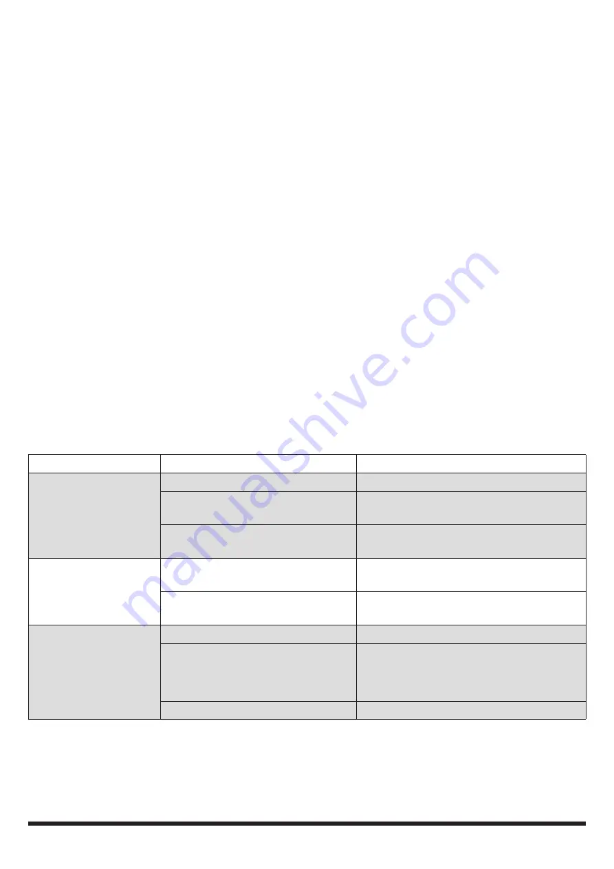
TROUBLE SHOOTING

Problem

Possible Cause(s)

Suggested Solution(s)

Excessive dust  

while blasting.

1. 


Abrasive media may be worn.

1. 


Replace the abrasive media.

2. 


Too much abrasive media in  

the hopper.

2. 


Remove excess abrasive media.

3. 


Loose air line or fitting connection. 3. 


Tighten the fitting and make sure the air 

lines are secure.

Uneven blasting action.

1. 


Too much abrasive media in  

the hopper.

1. 


Remove excess abrasive.

2. 


Moisture is present while blasting. 2. 


Check the air line to make sure that there 

is no moisture in it.

Inadequate speed or 

inefficiency of blast.

1. 


Abrasive media may be worn.

1. 


Replace the abrasive media.

2. 


Pressure is too low.

2. 


Increase the inlet pressure.

WARNING! Do not exceed the maximum 

pressure of 125 PSI.

3. 


Worn nozzle.

3. 


Replace the nozzle.

Summary of Contents for 8474116

Page 1: ...Please read and understand all instructions before use Retain this manual for future reference V 3 05 8474116 User Manual 20 Gallon Pressure Abrasive Blaster ...

Page 2: ...Keep this manual for the safety warnings precautions and operating inspection and maintenance instructions When this manual refers to a part number it refers to the included parts list WORK AREA 1 Operate in a safe work environment Keep your work area clean and well lit 2 Do not use in the presence of flammable gases or liquids 3 Keep anyone not wearing the appropriate safety equipment away from t...

Page 3: ...ng process is lessened 4 Do not exceed the maximum 125 PSI rating 5 Use only abrasives specifically intended for blasting 6 Disconnect the unit from the air source when not in use or before performing any maintenance or inspections 7 When searching for leaks use water with soap to spray onto the unit Do not use your hands to search for leaks in a pressurized system ABRASIVE BLASTING MEDIA PRECAUTI...

Page 4: ...od circulation to the hands past hand injuries nervous system disorders diabetes or Raynaud s Disease should not use this tool If you feel any medical symptoms related to vibrations such as tingling numbness and white or blue fingers seek medical attention as soon as possible 2 Do not smoke during use Nicotine reduces the blood flow to the hands and fingers increasing the risk of vibration related...

Page 5: ...steel copper aluminum or zinc Recommended Abrasive Blasting Media 1 Aluminum Oxide 2 Glass Bead 3 Steel Shot 4 Copper Slag Not Recommended Abrasive Blasting Media These blasting medias clog easier and require different nozzles and higher pressures 1 Baking soda grain starch 2 Crushed nutshells NOTE Store abrasive in a dry location Wet abrasive will clog the tool UNPACKING 1 Carefully remove the to...

Page 6: ...n the side of the intake manifold c Screw the open end of the joint pipe 13 into the threaded hole on the side of the filler pipe on the top of the tank NOTE Be sure that the manifold and gauge are vertical 4 Assemble the sand outlet valve into the hole at the bottom of the tank See figure 4 Fig 3 Fig 2 Fig 4 Fig 5 Attach the four parts in order threaded bushing 16 steel shut off valve 18B threade...

Page 7: ... into the fitting on the bottom of the tank 1 near the edge Use the cotter pin 3 to secure the front foot 4 to the tank 1 See figure 7 10 Before beginning operations check each connection double checking to ensure that all of the connections are tight and properly seated OPERATION LOADING ABRASIVES INTO THE TANK 1 Check your abrasive to be sure that it is dry and won t clog the steel abrasive shut...

Page 8: ...valve 18B to allow the abrasive to be moved from tank 1 This will allow the abrasive to mix with the air from the air hose 21 and flow into the abrasive hose 24 6 Squeeze the On Off control lever 42 on the deadman valve to begin the abrasive blasting process 7 When you have finished the abrasive blasting process release the On Off control valve 42 and close the steel abrasive shut off valve 18B to...

Page 9: ...rt that appears to be damaged should be carefully checked to determine that it would operate properly and perform its intended functions Check for alignment and binding of moving parts for broken parts or mounting fixtures or for any other condition that may affect proper operation NOTE Internal components of the unit will wear out after repeated exposure to the blasting process When the unit s pe...

Page 10: ...ry clean cloth or brush remove any contaminants from the unit and the deadman valve before placing the unit in storage DISPOSING OF THE TOOL 1 If your tool has become damaged beyond repair do not throw it out Take it to the appropriate recycling facility 2 Abrasive can be re used until it eventually breaks down or becomes dusty Dispose of waste abrasives in accordance with local authority regulati...

Page 11: ...Relief Valve 1 11 O Ring 1 12 Tank Filler Cap 1 13 Joint Pipe 1 14 Intake Manifold 1 15 Pressure Gauge 1 16 3 8 in Threaded Bushing 5 No Description Qty 17 Water Separator Filter 1 18 3 8 in Brass Air Supply Valve 1 18A 3 8 in Brass Shut Off Valve 1 18B 3 8 in Steel Abrasive Shut Off Valve 1 19 Threaded Bushing 1 20 Threaded Bushing 1 21 Air Hose 1 22 Abrasive Outlet Manifold 1 23 Hose Clamps 2 24...

Page 12: ...tion Qty 31 Upper Body 1 32 Lower Body 1 33 Metal Pipe 1 34 Intake Connector 1 35 Adaptor 1 36 Gasket 1 37 Ceramic Nozzle 4 38 Rubber Adaptor 4 39 Nozzle Cap Nut 1 40 Screw ST 4 2 x 16 4 No Description Qty 41 Screw ST 4 2 x 12 2 42 On Off Control Lever 1 43 Spring Pin 1 44 Spring 1 45 Pivot Block 1 46 Screw M3 x 25 1 47 Hard Alloy Pad 1 48 Nut M3 1 49 Hose Barb 1 ...

Page 13: ......

Page 14: ......

Page 15: ...4116 Manuel d utilisateur Vous devez lire et comprendre toutes les instructions avant d utiliser l appareil Conservez ce manuel afin de pouvoir le consulter plus tard Pulvérisateur d abrasif à pression de 20 gal ...

Page 16: ...outes les conditions et situations pouvant se produire L opérateur doit faire preuve de bon sens et prendre toutes les précautions nécessaires afin d utiliser l outil en toute sécurité REMARQUE Conservez ce manuel qui contient les avertissements de sécurité les précautions et les instructions de fonctionnement d inspection et d entretien Lorsque ce manuel fait référence à un numéro de pièce il fai...

Page 17: ...ures CONSIGNES DE SÉCURITÉ SPÉCIFIQUES 1 Lorsque vous utilisez l outil portez des vêtements lavables afin d éliminer la fine poussière résultant du processus de projection Des vêtements de protection jetables sont également recommandés 2 Portez un équipement de protection pour le visage comme des lunettes de sécurité ou un écran facial Un masque antipoussières qui éliminera les particules de pouss...

Page 18: ...et infliger des blessures corporelles ou endommager l aire de travail Fixez la conduite d air du compresseur à une structure fixe ou permanente au moyen de brides ou d attache câbles 6 Installez une soupape d arrêt sur conduite ou un régulateur afin de permettre une commande immédiate de l alimentation en air en cas d urgence même si un tuyau se fend PRÉCAUTIONS RELATIVES AUX VIBRATIONS Cet outil ...

Page 19: ...utiliser un certain nombre de matériaux abrasifs différents dans l outil Chaque type d abrasif a une application différente et un effet différent sur l objet à sabler Chaque type d abrasif peut aussi comporter des dangers et des risques pour la santé associés à son utilisation REMARQUE Veillez à lire Précautions relatives aux produits de projection abrasive dans la section consignes de sécurité sp...

Page 20: ...8 d Fixez le tuyau de jonction no 13 au collecteur no 14 2 Assemblez le filtre de séparateur d eau voir la figure 2 a Vissez les deux bagues filetées no 16 de chaque côté du filtre du séparateur d eau no 17 b Sur un côté fixez la soupape d alimentation d air en laiton no 18 à la bague filetée no 16 c Fixez ensuite la bague filetée no 19 de l autre côté de la soupape d alimentation d air d Lorsque ...

Page 21: ... sable à la soupape de type homme mort voir la figure 6 a Glissez les deux colliers de serrage pour tuyau no 23 sur chaque extrémité du tuyau d abrasif no 24 Enfoncez une extrémité du tuyau no 24 sur le raccord cannelé no 49 du collecteur de sortie d abrasif no 22 et l autre extrémité du tuyau no 24 sur le raccord cannelé no 49 de la soupape de type homme mort REMARQUE Les deux extrémités du tuyau...

Page 22: ...u les autres composants 2 Enfilez des vêtements de protection et utilisez un équipement de protection 3 Tournez la soupape d alimentation d air en laiton no 18 à la position OFF arrêt horizontale 4 Tournez la soupape d arrêt en laiton no 18B à la position ON marche verticale 5 Observez le manomètre no 15 et assurez vous qu il indique une pression nulle 6 Enlevez le bouchon de remplissage no 12 du ...

Page 23: ...uyau à air no 21 pour traverser ensuite le tuyau d abrasif no 24 6 Appuyez sur le levier de commande de marche arrêt no 42 sur la soupape de type homme mort pour entreprendre le processus de projection abrasive 7 Après avoir terminé le processus de projection abrasive relâchez la soupape de commande de marche arrêt no 42 et fermez la soupape d arrêt d abrasif en acier no 18B pour interrompre le fl...

Page 24: ... une plus grande surface ce qui réduit l efficacité de l outil Le compresseur doit aussi travailler plus fort pour maintenir la pression Vérifiez régulièrement la buse en céramique et remplacez la lorsque cela est nécessaire 2 Vérifiez toujours qu il n y a ni fissure ni fuite dans la soupape de type homme mort le tuyau et le réservoir Ces problèmes doivent être réparés immédiatement en raison des ...

Page 25: ...ous d avoir évacué la pression du réservoir avant de tenter d enlever le bouchon de remplissage du réservoir no 12 CONDITIONS USÉES Tel est habituellement le cas lorsqu une quantité excessive de poussière apparaît lors du sablage La poussière sera produite dans les cas suivants 1 Le produit de grenaillage abrasif est usé S il a perdu son aspect granulaire ou sphérique ou si une quantité élevée de ...

Page 26: ... usés 1 Remplacez les matériaux de sablage abrasifs 2 Trop grande quantité d abrasif à l intérieur 2 Éliminez tout excès de produit 3 Conduites d air ou raccords desserrés 3 Serrez le raccord et assurez vous que les conduites d air sont solides Opérations de grenaillage inégales 1 Trop grande quantité de produit abrasif dans le cabinet 1 Éliminez tout excès de produit 2 Présence d humidité lors du...

Page 27: ...Joint torique 1 12 Bouchon de remplissage de réservoir 1 13 Tuyau de jonction 1 14 Collecteur d admission 1 15 Manomètre 1 16 Bague filetée de 3 8 po 5 17 Filtre séparateur d eau 1 No Description Qté 18 Soupape d alimentation d air en laiton 3 8 po 1 18A Soupape d arrêt en laiton de 3 8 po 1 18B Soupape d arrêt d abrasif en acier de 3 8 po 1 19 Bague filetée 1 20 Bague filetée 1 21 Tuyau à air 1 2...

Page 28: ...ption Qté 31 Corps supérieur 1 32 Corps inférieur 1 33 Tuyau de métal 1 34 Raccord d admission 1 35 Adaptateur 1 36 Joint d étanchéité 1 37 Buse de céramique 4 38 Adaptateur de caoutchouc 4 39 Écrou de capuchon de buse 1 40 Vis ST 4 2 x 16 4 41 Vis ST 4 2 x 12 2 42 Levier de commande de marche arrêt 1 43 Tige de ressort 1 44 Ressort 1 45 Bloc de pivot 1 46 Vis M3 x 25 1 47 Plaquette d alliage dur ...

Reviews: