background image

Powered by Safety

®

28

Operating Procedures

PowlVac® Electrically Operated 5kV & 15kV G&T Device 

per ConEd Specification EO-2022-15 for ConEd CUSTOMER

 01.4IB.50026A

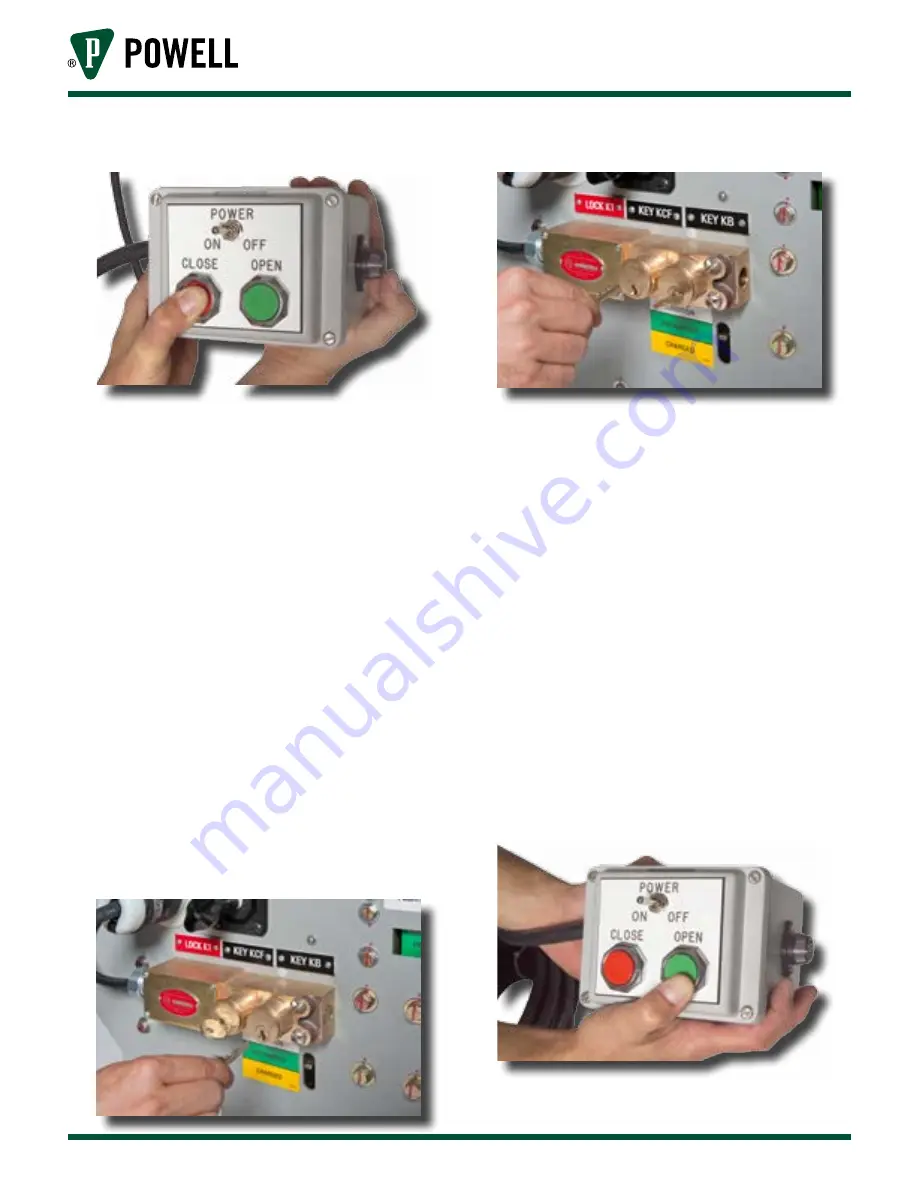
Figure 19  Press Close on Control Box

16. Unplug the remote control box from the 

120V power supply.

17. Move the control selector switch from the 

“Close” position to the “Off” position.

18. Disconnect the control box umbilical cord 

from the ground and test device.

19. Rotate key KCF in key lock K1.  Remove key 

KB from key lock K1.

20. Ground and test device can no longer be 

operated.

21. Secure key KB in lock box on premises.

B.  r

emovInG

 G

round

1.  Obtain key KB from lock box on premises.

2.  Transfer key KB to key lock K1 (Figure 20) 

and rotate key.  Key KB is now captive and 

key KCF is released (Figure 21).  The control 

circuit for the ground and test device is now 

enabled.

Figure 20  Inserting Key KB into Key Lock K1

Figure 21  Key KCF is Released from Key Lock K1

3. Verify that the control selector switch on 

the front of the ground and test device is in 

the “Off” (center) position (Figure 16).

4.  Connect the umbilical cord of the remote 

control box to the ground and test device 

(Figure 17).  Ensure the cord is locked into 

the connected position by turning the plug 

clockwise.

5.  Move the selector switch from the “Off” 

position to the “Open” position.

6.  From a safe distance, connect the ground 

and test device remote control box to a 

120VAC, 15 ampere power supply.

7.  Depress the “Open” push button switch 

on the control box (Figure 22) to open the 

ground and test device ground making 

switch.

Figure 22  Press Open on Control Box

Summary of Contents for PowlVac 1200

Page 1: ...01 4IB 50026A PowlVac Electrically Operated Ground and Test Device 5kV 15kV up to 50kA per ConEd Specification EO 2022 15 for ConEd CUSTOMER Powered by Safety ...

Page 2: ...erated 5kV 15kV G T Device per ConEd Specification EO 2022 15 for ConEd CUSTOMER Contact Information Powell Electrical Systems Inc www powellind com info powellind com Service Division PO Box 12818 Houston Texas 77217 2818 Tel 713 944 6900 Fax 713 948 4569 ...

Page 3: ...ut the safety alert symbol is used to address practices not related to personal injury CAUTION NOTICE NOTICE is used to address practices not related to personal injury Qualified Person For the purposes of this manual a qualified person as stated in NFPA 70E is one who has skills and knowledge related to the construction and operation of the electrical equipment and installations and has received ...

Page 4: ...Powered by Safety 01 4IB 50026A PowlVac Electrically Operated 5kV 15kV G T Device per ConEd Specification EO 2022 15 for ConEd CUSTOMER This page is intentionally left blank ...

Page 5: ... D Ground Making Switch 6 E Stored Energy Mechanism 7 F Test Ports 15 G Levering In Device 15 H Interlocking 16 I Shutters 16 J Operating Coils 16 1 Closing Coil 16 2 Shunt Trip Coil 16 K Control Relay 17 L Trip Paddle Interlock Switch 17 M Remote Control Box 17 N Key Locks 17 1 Key Lock K1 Keys KCF and KB 17 2 Key Lock K2 Keys KB and KC 19 3 Key Lock K3 Key KC 19 4 Key Lock K4 Keys KB and KD 19 5...

Page 6: ...23 3 Moving the Ground and Test Device from the Connected Position to the Disconnected Position 24 4 Removing the Ground and Test Device from the Upper Switchgear Compartment 24 Ch 5 Operating Procedures 25 A Applying Ground 25 B Removing Ground 28 C Procedure for Testing Feeder 29 D Testing Ports 31 E Removing Test Probes 31 Ch 6 Maintenance 34 A General Description 34 1 Introduction 34 2 Inspect...

Page 7: ...res 43 1 Grounding Switch Movable Contact 43 2 Grounding Switch Stationary Contacts 43 3 Closing Coil Assembly 44 4 Charging Motor Assembly 44 5 Shunt Trip Coil 45 6 Control Relay 45 7 Latch Check Switch 46 8 Trip Paddle Interlock Switch 46 9 Motor Cutoff Switch Assembly 47 10 Auxiliary Switch 47 11 Primary Contact Spring Assembly 48 12 Ground Shoe Finger Assembly 48 Contents ...

Page 8: ...ock K1 25 Figure 12 Key KB into Key Lock K2 and Depressing Manual Trip Push Button 26 Figure 13 Inserting Key KC into Key Lock K3 26 Figure 14 Transfer Key KC to Key Lock K2 26 Figure 15 Transfer Key KB to Key Lock K1 27 Figure 16 Selector Switch in Off Position 27 Figure 17 Connecting Control Box to Device 27 Figure 18 Selector Switch in Closed Position 27 Figure 19 Press Close on Control Box 28 ...

Page 9: ...r act is performed requiring physical contact with the electrical working components or wiring of this equipment the power supply must be disconnected Failure to follow this warning may result in injury or death NOTICE The information in this instruction bulletin is not intended to explain all details or variations of the Powell equipment nor to provide for every possible contingency or hazard to ...

Page 10: ...placement 5 Information for ordering renewal parts 6 Illustrations photographs and description of the ground and test device The illustrations contained in this document may not represent the exact construction details of each particular type of ground and test device The illustrations in this document are provided as general information to aid in showing component locations only All illustrations...

Page 11: ...easurement and test instruments intended for use on electrical systems 1000 V and below 6 Where the possibility of induced voltages or stored electrical energy exists ground the phase conductors or circuit parts before touching them Where it could be reasonably anticipated that the conductors or circuit parts being deenergized could contact other exposed energized conductors or circuit parts apply...

Page 12: ...t be observed 1 Do not close the grounding switch on an energized circuit The circuit to be grounded should always be treated as energized until proven otherwise 2 Use great care when opening the test port shutters to gain access to the test receptacles The test receptacles should always be treated as energized circuits until proven otherwise 3 Any test device plugged into the test receptacles mus...

Page 13: ...all primary circuit connections to make certain that they are clean and tight 12 Take extreme care while using this device to avoid contacting live or hot energized terminals E Safety Labels The equipment described in this document has DANGER WARNING CAUTION and instruction labels attached to various locations All equipment DANGER WARNING CAUTION and instruction labels shall be observed when the g...

Page 14: ...hose applied to the power circuit breaker it is designed to temporarily replace for grounding and testing purposes The rating nameplate Figure 1 i on the front of the device will give the ratings applicable to any individual device C Primary Disconnect Stabs The ground and test device has three 3 primary disconnect stabs consisting of an upper or lower device Figure 2a f Figure 2b a similar in des...

Page 15: ... lower front cover Its output shaft is screwed to a coupler which insert into the eccentric drive shaft This shaft is supported in the needle bearings in the mechanism frame side sheets and transmits the motor torque from the left to the right side of the mechanism When the motor is energized the eccentric shaft rotates and causes the driving arm links to pivot about the cam shaft Figure 3 l The d...

Page 16: ...1 4IB 50026A Figure 1 Ground Test Device with Probes a Test Probes shown with test leads attached b Key Lock K5 c Racking Assembly d Levering In Shutter e Key Lock K3 f View Window g Power Receptacle h Control Selector Switch i Nameplate j Key Lock K4 k Key Lock K1 l Key Lock K2 m Close Coil n Manual Push to Trip Paddle a b c d e f g h i j k l m n ...

Page 17: ...ing In Shutter Interlock f Lower Primary Disconnecting Device g Ground Connection h Anti Rollout Latch i Wheel a b c d e f g i h Figure 2b Ground Test Device Right View with Upper Primaries a c d e f g i h b a Upper Primary Disconnecting Device b Crank Arm Roller c Racking Gear d Racking Crank Arm e Worm Gear f Levering In Shutter Interlock g Ground Connection h Anti Rollout Latch i Wheel ...

Page 18: ... Figure 5 The linkage is restrained from movement by the secondary trip prop acting on the primary trip prop roller The component of force tends to make the primary trip prop move downward but it is restrained by the secondary trip prop face acting on the primary trip prop roller The clearance between the primary trip prop roller and the secondary trip prop is controlled by the primary trip prop a...

Page 19: ...ew a Grounding Switch Stationary Contacts b Grounding Switch Moveable Contacts c Auxiliary Switch d Ground Bus e Control Relay f Stored Energy Mechanism g Pawl Return Spring Weldment h Ratchet Wheel i Pawl Support Arm j Eccentric Roller k Crank Arm l Cam Shaft a b c d e f h k i j l g ...

Page 20: ...cally Operated 5kV 15kV G T Device per ConEd Specification EO 2022 15 for ConEd CUSTOMER 01 4IB 50026A Figure 4 Mechanism Left View a Charging Motor b Shunt Trip Coil when furnished c Motor Cutoff Switch d Connecting Rod e Close Latch Adjusting Screw a b c d e ...

Page 21: ... f g h i j k m a Center Phase Operating Lever b Jack Shaft c Primary Trip Prop Adjusting Screw d Main Cam Roller e Primary Trip Prop f Main Drive Cam g Primary Trip Prop Roller h Secondary Linkage Roller i Cam Shaft j Trip Bar k Secondary Trip Latch l Reset Spring m Secondary Trip Prop Adjusting Screw l ...

Page 22: ...rically Operated 5kV 15kV G T Device per ConEd Specification EO 2022 15 for ConEd CUSTOMER 01 4IB 50026A Figure 6 Cam and Fundamental Link Positions A Device Open Springs Charged Links Reset B Device Closed Springs Discharged C Device Open Springs Discharged ...

Page 23: ...st ports Grooves around the circumference of the test probes allow them to be held captive in the test ports by slots in the shutters which cover the test ports This feature can be used with interlocks to control the sequence of test operation G Levering In Device The ground and test device is moved between the disconnected and connected positions by the levering in device This consists of a shaft...

Page 24: ...in it The back end of the shutter arm has another pin which must drop into one of these notches in order to raise the shutter and release the trip paddle The two notches are positioned so that the pin on the shutter will enter one notch when the ground and test device is in the fully inserted position and the other notch when the device is in the fully withdrawn position In all other positions of ...

Page 25: ... conductor power cord The cord is permanently attached to the control box with a four conductor twist lock type receptacle at the ground and test device end Figure 8 Remote Control Box N Key Locks The PowlVac PV E 60600G13 is provided with numerous key lock interlocks and include 1 Key Lock K1 Keys KCF and KB The key lock K1 interlock is a two cylinder lock used to electrically enable or disable t...

Page 26: ...ional FU 15A PB NO PB NO Optional 14 3 C SO Cord B W G 120V 15A 3 Prong Plug W G B C T 1 1 1 2 2 2 14 4 C W X Y Z LS Y Y Y M M1 J 4 7 1 2 6 9 4 4C NO C 43 C 57 b 57 b LS LCS NO C NO C C NC IS A B 43 C 2 2C 43 T 1 2 1 1C 3C 3 43 T 57 a NC C CC 1 2 TC 43 Contacts Handle End Odd Even Trip Off Close 1 2 3 4 2 2C 1C 1 4 4C 3C 3 Similar to 10AA041 Except Engrave Trip Off Close T r i p Off Close 00 K1 1 ...

Page 27: ...the insertion of the ground and test device into the connected position in the circuit breaker compartment When the ground and test device is in the connected position the K3 interlock prevents access to the ground and test mounted racking device input shaft This action prevents the removal of the ground and test device from the connected position With the KC key inserted and the locking bolt retr...

Page 28: ...probe locking position O Control Selector Switch A control selector switch Figure 1 h is mounted on the front of the ground and test device This selector switch enables and disables the closing and tripping function of the ground and test device The selector switch is a three position rotary switch that operates in association with the remote OPEN CLOSE push button control box The snap action posi...

Page 29: ...and test device has been removed from its shipping pallet it may be rolled on its own wheels on a level surface This is the preferred way of handling the ground and test device When rolling the ground and test device it should be pushed and steered by the steel frame or the front cover Do not handle or move the ground and test device by the primary disconnecting devices as damage may occur CAUTION...

Page 30: ... be kept below 60 or a dew point of 15 C 59 F The equipment should be stored in such a manner as to leave all doors and panels accessible for inspection The equipment must be inspected on a routine basis to assure its integrity 3 The auxiliary control devices ship loose material and protective relays must also be protected This includes items such as battery chargers UPS systems lighting installat...

Page 31: ... at the sides of the device point in the direction of the main disconnects Each ground and test device and each compartment is provided when required with a coding plate designed to ensure that no device with less than the required voltage or momentary current rating is placed in any compartment If attempting to insert an improperly rated device into the switchgear these coding plates will interfe...

Page 32: ... levering in shutter returning it to its normal closed position The trip paddle will be released by this action and will return to its normal position The maximum force required on the racking handle for normal insertion of the ground and test device will not exceed 35 ft lbs Excessive force may damage the device or the switchgear 3 Moving the Ground and Test Device from the Connected Position to ...

Page 33: ...y a ground to an energized line or bus The operator should ensure that the circuit to be grounded is deenergized before closing the grounding switch CAUTION Because the two high construction of PowlVac metal clad switchgear requires the bus connections to be located on the upper disconnect stabs of some compartments and the lower disconnect stabs of other compartments it is vital that the operator...

Page 34: ...e 13 The KC key is now captive Pull the racking access shutter fully down The ground and test device racking shaft is now accessible Key lock K3 is blocked from operation with the racking access shutter in the down position Figure 13 Inserting Key KC into Key Lock K3 7 Install the racking handle and rotate the handle clockwise to move the ground and test device into the Connected position The conn...

Page 35: ...r Switch in Off Position 12 Connect the umbilical cord of the remote control box to the ground and test device Figure 17 Ensure the cord is locked into the connected position by turning the plug clockwise Figure 17 Connecting Control Box to Device 13 Move to control selector switch from OFF position to Close position Figure 18 Figure 18 Selector Switch in Closed Position 14 From a safe distance co...

Page 36: ...0 and rotate key Key KB is now captive and key KCF is released Figure 21 The control circuit for the ground and test device is now enabled Figure 20 Inserting Key KB into Key Lock K1 Figure 21 Key KCF is Released from Key Lock K1 3 Verify that the control selector switch on the front of the ground and test device is in the Off center position Figure 16 4 Connect the umbilical cord of the remote co...

Page 37: ...isconnected position Key KC is now released 16 Transfer key KC to key lock K2 Fully depress the manual trip operator and rotate key KC Release the manual trip operator The key KC is now captive and key KB is released 17 Transfer key KB to key lock K1 Figure 20 and rotate The ground and test device control circuit is now enabled Key KB is now captive and key KCF is now released 18 Remove the ground...

Page 38: ... KB The ground and test device control circuit is now enabled Key KB is now captive and key KCF is now released 17 Verify that the control selector switch on the front of the ground and test device is in the Off center position Figure 16 18 Connect the umbilical cord of the remote control box to the ground and test device Figure 17 Ensure the cord is locked into the connected position by turning t...

Page 39: ... of the test probe may be energized at a voltage above ground potential CAUTION The test probes are not high current devices They are suitable for testing procedures such as high potential testing phasing out circuits phase rotation testing and primary voltage measurements Since the test probes give access to primary circuits it is essential that any test apparatus connected to the test probes be ...

Page 40: ...e Figure 17 Ensure the cord is locked into the connected position by turning the plug clockwise 21 Move the control selector switch from the Off position to the Open position 22 From a safe distance connect the ground and test device remote control box to a 120VAC 15 ampere power supply 23 Depress the Open push button switch on the remote control box Figure 22 to open the ground and test device gr...

Page 41: ...anual trip operator and rotate key KC Release the manual trip operator Key KC is now captive and key KB is now released 33 Transfer key KB to key lock K1 Rotate key KB The ground and test device control circuit is now enabled Key KB is now captive and the KCF key is released 34 Remove the ground and test device from the compartment 35 Remove key KCF from key lock K1 36 Secure key KCF in a lock box...

Page 42: ...torage conditions If the ground and test device is used relatively infrequently the interval between inspections may be longer than a year but may include only a few operations When the ground and test device has been in storage for an extended period of time it is recommended that it be inspected and cleaned before being used See Ch 4 Installation C Storage for storage recommendations Follow thos...

Page 43: ... parts Operate the grounding switch several times Operate the levering in mechanism through one or two complete cycles and check for smoothness of operation 2 Lubrication Powell offers a complete lubrication kit Powlube 104 which contains all the lubricants required for maintaining the ground and test devices Powlube 104 consists of 1 A grease 1 B grease and 1 C oil Prior to March 2014 Powell prov...

Page 44: ...ller Needle Bearings Figure 25 k C Oil Pawls Figure 25 l C Oil Close Latch Shaft Face Figure 25 m A Grease Apply a light coating of grease and remove all excess Ratchet Wheel Figure 25 n A Grease Jackshaft Lever Pins passing through Operating Rod Clevises no image available C Oil Fixed Link Pin Figure 25 o C Oil Apply to penetrate where pin passes through end link Main Closing Spring Guide Rod Fig...

Page 45: ...n Closing Spring Guide Rod q Primary Trip Prop Shaft Support Bearing r Primary Trip Prop Shaft Roller a Main Primary Disconnect Fingers b Grounding Switch Hinges c Grounding Switch Contacts d Levering In Device Worm and Wheel e Worm Shaft Bearings f Levering In Shaft Support Bearings y Motor Cutoff Switch Cam z Fundamental Link aa Fundamental Linkage Cam s Open Close Flag Drive Lever Pin t Flag Su...

Page 46: ...ng screw Figure 5 m so that the overlap of the secondary trip prop on the primary trip prop roller is approximately 0 125 Adjust the primary trip prop adjusting screw Figure 5 c so that with the main linkage in the reset position the clearance between the primary trip prop roller and the secondary trip prop is 0 005 to 0 015 With a 0 015 wire gauge between the trip bar lever and the secondary trip...

Page 47: ...times to ensure that the electrical control system works properly Refer to Ch 5 Operating Procedures C Grounding Switch Area 1 Routine Maintenance Lubricate the blades as shown in Table A Examine the contact areas both moving and stationary for evidence of overheating pitting cracking or other damage Any damaged parts should be replaced 2 Moving Contact Adjustments There are two factory adjustment...

Page 48: ...tch and recheck the gap Repeat as necessary to achieve optimum adjustment of the gap Figure 27 Ground Switch Contacts 2 1 8 1 4 to 5 16 c Hinge Bolt Disconnect the operating rod at the movable contact by removing the pin With the movable contact not touching the stationary contacts apply a force gauge to the outer end of the contacts The hinge bolt should be tightened so that the force necessary t...

Page 49: ...insulation tester or with and AC high potential tester The AC high potential test should be made at 1125V 60Hz for one minute The charging motor must be disconnected at its connection plug prior to testing the control circuit The motor itself may be similarly tested at a voltage not to exceed 675V 60Hz Be sure to remove any test jumpers and reconnect the charging motor when the tests are complete ...

Page 50: ... the severity of the service and the time required to secure replacements parts Since parts may be improved periodically renewal parts may not be identical to the original parts Table B lists the recommended spare parts to be carried in stock by the user The recommended quantity is not specified This must be determined by the user based on the application It is recommended that one set of parts be...

Page 51: ...isible break and securely grounded Do NOT start to work on a closed ground and test device or a ground and test device with the main closing spring charged CAUTION Perform the following steps to replace the grounding switch movable contact a Remove upper portion of ground and test device front cover b With grounding switch in OPEN position remove two bolts holding movable contact to top of moving ...

Page 52: ...with the main closing spring charged CAUTION Perform these steps to replace the closing coil assembly a Remove the upper portion of the ground and test device front cover b Unplug the closing coil from the wiring harness c Remove the two bolts holding the closing coil assembly to the lower front cover and withdraw the closing coil from the front of the ground and test device d Insert new closing c...

Page 53: ...d Insert the new trip coil assembly into the device bolt it into place and plug it into the wiring harness e With the mechanism in the reset position check the gap between the trip coil armature and the trip lever extending from the trip shaft This gap should be between and If necessary bend the trip lever slightly to achieve this setting f Close and trip the grounding switch electrically several ...

Page 54: ...in this instruction bulletin f Close the grounding switch electrically several times to ensure that the mechanism is working properly g Replace the upper front cover 8 Trip Paddle Interlock Switch The trip paddle interlock switch is located on the right side of the mechanism just above the floor pan Figure 26 d It is accessible from the rear of the ground and test device Ensure that the control ci...

Page 55: ... 10 Auxiliary Switch The auxiliary switch is located on the left hand side panel of the ground and test device Figure 3 c Ensure that the control circuits are deenergized and the ground and test device is deenergized disconnected by means of a visible break and securely grounded Do NOT start to work on a closed ground and test device or a ground and test device with the main closing spring charged...

Page 56: ...erly Note Springs are to be installed in every other slot in fingers top center and bottom The second and fourth slots are empty 12 Ground Shoe Finger Assembly The ground shoe assembly is located at the rear edge of the ground and test device floor pan between the center and right poles Figure 2a g Ensure that the control circuits are deenergized and the ground and test device is deenergized disco...

Page 57: ...818 Houston TX 77217 Tel 713 944 6900 Fax 713 948 4569 www powellind com info powellind com 2006 Powell Industries Inc All rights reserved 5kV 15kV 50kA per ConEd Specification EO 2022 15 for ConEd CUSTOMER 01 4IB 50026A PowlVac Electrically Operated Ground Test Device September 2014 ...

Reviews: