background image

18

STORAGE

Immediately prepare your snow thrower for storage at 

the end of the season or if the unit will not be used for 30 

days or more.

WARNING: Never store the snow 

thrower with gaso line in the tank in side 

a build ing where fumes may reach an 

open flame, spark or pilot light as on a 

fur nace, water heater, clothes dryer or 

gas ap pli ance.  Allow the engine to cool 

be fore storing in any enclosure.

SNOW THROWER

When snow thrower is to be stored for a period of time, 

clean it thor oughly, re move all dirt, grease, leaves, etc. 

Store in a clean, dry area.
1.  Clean entire snow thrower (See “CLEANING” in the 

Main te nance section of this manual).

2.  Inspect and replace belts, if necessary (See “TO RE-

 PLACE BELTS” in the Service and Adjustments sec tion 

of this manual).

3.  Lubricate as shown in the Main te nance sec tion of this 

man u al.

4.  Be sure that all nuts, bolts, screws, and pins are securely 

fas tened. Inspect moving parts for damage, breakage 

and wear. Replace if nec es sary.

5.  Touch up all rusted or chipped paint surfaces; sand 

lightly before painting.

ENGINE

See engine manual.

FUEL SYS TEM
IMPORTANT

:  It is important to prevent gum deposits from 

forming in essential fuel system parts such as carburetor,  

fuel hose, or tank during storage. Also, alcohol blended 

fuels (called gasohol or using ethanol or methanol) can 

attract moisture which leads to separation and formation 

of acids during storage. Acidic gas can damage the fuel 

system of an engine while in storage.

•  Empty the fuel tank by starting the engine and letting 

it run until the fuel lines and car bu re tor are empty.

•  Never use engine or carburetor cleaner prod ucts in 

the fuel tank or permanent damage may occur.

•  Use fresh fuel next season.

NOTE: 

 Fuel stabilizer is an acceptable alternative in min-

 i miz ing the formation of fuel gum deposits during stor age. 

Add stabilizer to gasoline in fuel tank or storage container. 

Always follow the mix ratio found on stabilizer container. 

Run engine at least 10 min utes after adding stabilizer to 

allow the stabilizer to reach the carburetor. Do not empty 

the gas tank and carburetor if using fuel stabilizer.

ENGINE OIL

Drain oil (with engine warm) and replace with clean engine 

oil. (See “ENGINE” in the Maintenance section of this 

man ual).

CYLINDER

1.  Remove spark plug.
2.  Pour one ounce (29 ml) of oil through spark plug hole 

into cylinder.

3.  Pull recoil starter handle slowly a few times to dis trib ute 

oil.

4.  Replace with new spark plug.

OTHER

•  Remove safety ignition key; store it in a safe place. 
•  Do not store gasoline from one season to another.
•  Replace your gasoline can if your can starts to rust. 

Rust and/or dirt in your gasoline will cause problems.

• 

If possible, store your snow thrower indoors and cover 

it to protect it from dust and dirt.

•  Cover your snow thrower with a suitable pro tec tive 

cover that does not retain moisture. Do not use plastic. 

Plastic cannot breathe, which allows con den sa tion to 

form and will cause your snow thrower to rust.

IMPORTANT

: Never cover snow thrower while engine/ex-

haust area is still warm.

Summary of Contents for 430005

Page 1: ...ways Wear Eye Protection During Operation IMPORTANT MANUAL Do Not Throw Away WARNING Read the Owner s Manual and follow all Warnings and Safety Instructions Failure to do so can result in serious injury 430005 Rev 2 09 01 09 AP SR Printed in the U S A ...

Page 2: ... the machine Operation 1 Do not put hands or feet near or under rotating parts Keep clear of the discharge opening at all times 2 Exercise extreme caution when operating on or cross ing gravel drives walks or roads Stay alert for hidden hazards or traffic 3 After striking a foreign object stop the engine motor remove the wire from the spark plug disconnect the cord on electric motors thoroughly in...

Page 3: ...fe working condition 2 Never store the machine with fuel in the fuel tank inside a building where ignition sources are present such as hot water heaters space heaters or clothes dryers Allow the engine to cool before storing in any enclosure 3 Always refer to operator s manual for important details if the snow thrower is to be stored for an extended period 4 Maintain or replace safety and instruct...

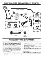
Page 4: ... nuts washers bolts etc necessary to complete the assembly have been placed in the parts bag To ensure safe and proper operation of your snow thrower all parts and hardware you assemble must be tightened securely Use the correct tools as necessary to ensure proper tightness REMOVE SNOW THROWER FROM CARTON 1 Remove all accessible loose parts and parts boxes from carton ASSEMBLY PRE OPERATION 2 Cut ...

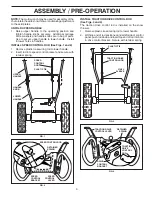
Page 5: ...iner spring TRACTION DRIVE CONTROL ROD DRIVE CONTROL BRACKET RETAINER SPRING TRACTION DRIVE CONTROL LEVER FIG 4 TRACTION DRIVE CONTROL ROD VINYL SLEEVE FIG 3 PLASTIC TIE NOTE The multi wrench may be used for assembly of the chuterotatorheadtosnowthrowerandmakingadjustments to the skid plates UNFOLD UPPER HANDLE 1 Raise upper handle to the operating position and tighten handle knobs securely Additi...

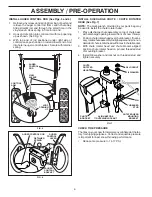
Page 6: ...ipping purposes Correct and equal tire pressure is important for best snow throwing performance Reduce tire pressure to 14 17 PSI CHUTE ROTATER HEAD 3 8 WASHER 3 8 LOCKNUT THREADED STUD PIN ROTATER HEAD MOUNTING BRACKET CHUTE BRACKET FIG 7 ALIGN BEFORE TIGHTENING LOCKNUT AUGER CONTROL LEVER AUGER CONTROL ROD AUGER CONTROL BRACKET RETAINER SPRING FIG 6 INSTALL AUGER CONTROL ROD See Figs 5 and 6 1 R...

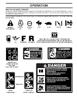
Page 7: ...s Save this manual for future reference These symbols may appear on your snow thrower or in literature supplied with the product Learn and understand their meaning FORWARD PRIMER IGNITION KEY INSERT TO START AND RUN PULL OUT TO STOP READ AND FOLLOW ALL SAFETY INFORMATION AND INSTRUCTIONS BEFORE USE OF THIS PRODUCT KEEP THESE INSTRUCTIONS FOR FUTURE REFERENCE DANGER OR WARNING REVERSE SNOW DISCHARG...

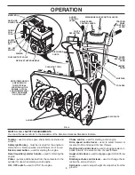
Page 8: ...start button used for starting the engine Recoil auxiliary starter handle used for starting the engine Primer pumps additional fuel from the carburetor to the cylinder for use when starting a cold engine ON OFF switch used to STOP the engine MEETS A N S I SAFETY REQUIREMENTS Our snow throwers conform to the standards of the American National Standards Institute TRACTION DRIVE CONTROL LEVER DISCHAR...

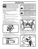
Page 9: ...se severe injury from contact or from ma terial thrown from the discharge chute Keep the area of operation clear of all persons small children and pets at all times including startup WARNING If the discharge chute or augerbecomeclogged shut offengine andwaitforallmovingpartstostop Use the clean out tool NOT YOUR HANDS to unclog the chute and or auger The DIRECTION in which snow is to be thrown is ...

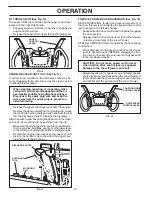
Page 10: ...sare in the direction of discharge before restarting engine AUGER CONTROL LEVER FIG 13 Restart the engine then squeeze the auger control lever to the handle to clear snow from the auger hous ing and the discharge chute CLEAN OUT TOOL FIG 14 MOUNTING CLIP DISCHARGE CHUTE TO MOVE FORWARD AND BACKWARD See Fig 15 SELF PROPELLING forward and reverse movement of the snow thrower is controlled by the tra...

Page 11: ...he fuel system should be emptied before storage of 30 days or longer Empty the gas tank start the engine and let it run until the fuel lines and carburetor are empty Use fresh fuel next season SeeStorageInstructionsforadditional information Never use engine or carburetor cleaner products in the fuel tank or permanent damage may occur SCRAPER BAR See Fig 16 The scraper bar is not adjustable but is ...

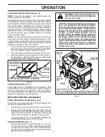
Page 12: ...rower engine is equipped with a recoil starter COLD START 1 Insert safety ignition key tied to recoil start cord into ignition slot until it clicks DO NOT turn the key Keep the extra safety ignition key in a safe place 2 Place ON OFF switch in ON position 3 Rotate choke control to FULL position 4 Push the primer four 4 times if the temperature is below 15 F or two 2 times if temperature is between...

Page 13: ...edule in this manual NOTE Use only Original Equipment Manufacturer OEM parts to service this unit Failure to do so can cause the unit to malfunction and pose a risk of injury to the operator BEFORE EACH USE 1 Check engine oil level 2 Check for loose fasteners 3 Checkcontrolstobesuretheyarefunctioningproperly LUBRICATION Keep your snow thrower well lubricated See LUBRICATION CHART SNOW THROWER Alwa...

Page 14: ...act with plug 2 Clean area around drain plug 3 Remove drain plug and drain oil in a suitable container 4 Install drain plug and tighten securely 5 Wipe off any spilled oil from snow thrower and engine 6 Install left wheel if removed for draining oil Be sure to install klick pin into proper hole in wheel axle See TO REMOVE WHEELS in the Service and Adjustments section of this manual 7 Remove oil fi...

Page 15: ... To replace the shear bolts 1 Disengage all controls and move throttle control to STOP position Wait for all moving parts to stop 2 Remove safety ignition key and disconnect spark plug wire from spark plug Place wire where it cannot come in contact with spark plug 3 Align hole in auger hub with hole in auger shaft and install a new 1 4 20 x 2 shear bolt Install 1 4 20 lock nut and tighten securely...

Page 16: ...vice center department NOTE It is recommended that both the auger and traction drive belt be replaced at the same time The V belts on your snow thrower are of special construc tion and should be replaced by original equipment manu facturer OEM belts available from your nearest service center department Using other than OEM belts can cause personal injury or damage to the snow thrower WARNING Belt ...

Page 17: ...ous and will void the warranty If you think the engine governed high speed needs adjusting contact a qualified service center which has proper equipment and experience to make any necessary adjustments TO REMOVE WHEELS See Fig 21 Remove the klik pin and remove wheel from axle IMPORTANT When installing wheel be sure to use the in nermost hole in axle and the wheel hub hole To disengage drive system...

Page 18: ... system of an engine while in storage Empty the fuel tank by starting the engine and letting it run until the fuel lines and carburetor are empty Never use engine or carburetor cleaner products in the fuel tank or permanent damage may occur Use fresh fuel next season NOTE Fuel stabilizer is an acceptable alternative in min imizing the formation of fuel gum deposits during storage Add stabilizer to...

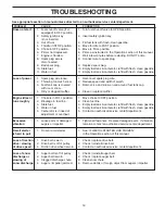
Page 19: ...osition 1 Move choke to OFF position runs roughly 2 Blockage in fuel line 2 Clean fuel line 3 Stale fuel 3 Empty fuel tank carburetor refill with fresh clean gasoline 4 Water in fuel 4 Empty fuel tank carburetor refill with fresh clean gasoline 5 Carburetor is in need of 5 Contact an authorized service center department adjustment or overhaul Excessive 1 Loose parts or damaged 1 Tighten all fasten...

Page 20: ... inches 1 inch 25 4 mm IMPORTANT Use only Original Equipment Manufacturer O E M replacement parts Failure to do so could be hazardous damage your snow thrower and void your warranty 9 01 07 004 D 2 EXPLODED 11 11 1 2 3 4 5 12 12 13 14 15 10 6 7 9 9 8 16 17 18 19 11 11 21 22 23 24 25 31 31 32 30 33 37 37 29 34 35 20 21 22 23 26 27 28 36 ...

Page 21: ...EAN OUT TOOL 8 405400 TOOL CLIP 9 73800400 NUT 1 4 20 10 74780426 SCREW 1 4 20 X 625 11 427942 NUT 5 16 18 12 163183 SCREW 5 16 18 X 625 13 19111507 WASHER 14 10040500 LOCKWASHER 5 16 15 74940516 SCREW 5 16 18 X 1 00 16 180355 CARRIAGE BOLT 17 194189 SCREW 13 16 X 625 18 407760 PLUG 19 407761 GEARBOX COVER RH 20 407766 GASKET 21 407770 SEAL 22 407762 BEARING 23 174697 THRUST WASHER 1 00 24 407763 ...

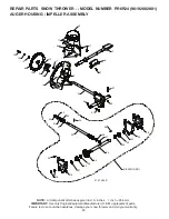
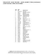
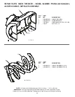
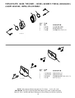
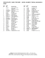
Page 22: ...thrower and void your warranty KEY PART NO NO DESCRIPTION REPAIR PARTS SNOW THROWER MODEL NUMBER PR6R24 96192002801 AUGER HOUSING IMPELLER ASSEMBLY KEY PART NO NO DESCRIPTION 1 2 3 5x 4 5x 01 07 001 A 1 404928X428 AUGER HOUSING 2 404931X479 SCRAPPER BAR 3 72270505 CARRIAGE BOLT 5 16 18 X 625 4 155377 NUT 5 16 18 2 1 01 07 017 A 1 420493X479 AUGER ASSEMBLY LH 24 2 420494X479 AUGER ASSEMBLY RH 24 ...

Page 23: ... replacement parts Failure to do so could be hazardous damage your snow thrower and void your warranty 1 174762X479 SKID PLATE LH 2 178777X479 SKID PLATE RH 3 72270506 CARRIAGE BOLT 5 16 18 X 75 4 751153 NUT 5 16 18 REPAIR PARTS SNOW THROWER MODEL NUMBER PR6R24 96192002801 AUGER HOUSING IMPELLER ASSEMBLY 1 1 2 3 2 3 01 07 024 B 1 420478 AUGER BEARING 2 411939 BEARING PLUG 3 179582 SCREW 5 16 18 X ...

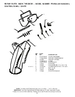
Page 24: ...so could be hazardous damage your snow thrower and void your warranty REPAIR PARTS SNOW THROWER MODEL NUMBER PR6R24 96192002801 CONTROL PANEL CHUTE 1 404770X428 CHUTE WELDMENT 2 178633X428 DEFLECTOR WELDMENT 3 420325 DEFLECTOR SEAL 4 179096X479 STRAP 5 189713X428 KNOB BLACK 6 128415 POP RIVET 7 185600 SHOULDER BOLT 1 4 20 X 704 8 72270505 CARRIAGE BOLT 5 16 18 X 625 9 191730 NUT 1 4 20 10 155415 W...

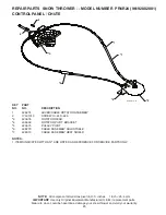
Page 25: ...y KEY PART NO NO DESCRIPTION REPAIR PARTS SNOW THROWER MODEL NUMBER PR6R24 96192002801 CONTROL PANEL CHUTE 1 2 2 3 4 5 6 7 01 09 010 B 1 428272 LEVER CABLE ROTATOR ASSEMBLY 2 17501010 SCREW 10 24 X 625 3 420678 ROTATOR HEAD 4 405932 ROTATOR PIVOT BRACKET 5 420675 PULLEY PIVOT 6 428273 CABLE ASSEMBLY ADJUSTABLE 7 428310 CABLE ASSEMBLY HEAT SHIELD NOTES 1 ITEMS INDICATED WITH AN ARE LISTED AS REFERE...

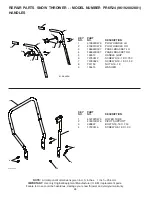
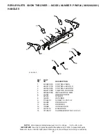
Page 26: ... REPAIR PARTS SNOW THROWER MODEL NUMBER PR6R24 96192002801 HANDLES 1 2 3 4 4 4 4 01 05 004 C 1 419797X479 LOWER TUBE 2 418313X479 PIVOT SUPPORT 3 428867 BOLT 5 16 18 X 750 4 17000616 SCREW 3 8 16 X 1 00 1 2 3 4 5 5 6 6 7 7 8 8 8 9 9 01 08 003 A 1 419800X479 PLOW HANDLE LH 2 419801X479 PLOW HANDLE RH 3 196944X007 PANEL BRACKET LH 4 196943X007 PANEL BRACKET RH 5 199513 HANDLE GRIP 6 74780512 SCREW 5...

Page 27: ...NOW THROWER MODEL NUMBER PR6R24 96192002801 HANDLES 10 11 1 2 3 4 5 6 7 7 9 9 8 8 12 12 13 13 14 14 01 08 002 F 1 412683X479 CONTROL PANEL 2 424517X179 CONTROL LEVER LH 3 424516X479 CONTROL LEVER RH 4 426917X008 TRACTION ROD ARM 5 426918X008 IMPELLER ROD ARM 6 412677 INTERLOCK BAIL 7 421613 SPACER 8 169675 RETAINER 9 17060410 SCREW 1 4 20 X 62 10 414280 KNOB BLACK 11 414281 KNOB RED 12 178899 HAND...

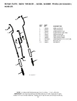
Page 28: ...and void your warranty KEY PART NO NO DESCRIPTION REPAIR PARTS SNOW THROWER MODEL NUMBER PR6R24 96192002801 HANDLES 10 10 10 1 2 3 4 5 5 6 7 9 8 01 12 001 E 1 180480 IMPELLER ROD 2 405740 TRACTION ROD 3 180445 SHIFTER ROD TOP 4 187716 SHIFTER ROD BOTTOM 5 180447 SPRING SLEEVE 6 178669 IMPELLER SPRING 7 180926 TRACTION SPRING 8 72270505 CARRIAGE BOLT 5 16 18 X 625 9 155377 NUT 5 16 18 10 169675 RET...

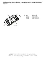
Page 29: ...ufacturer O E M replacement parts Failure to do so could be hazardous damage your snow thrower and void your warranty KEY PART NO NO DESCRIPTION REPAIR PARTS SNOW THROWER MODEL NUMBER PR6R24 96192002801 HANDLES 01 10 001 B 1 3 3 2 2 1 183352 CONSOLE PANEL 2 184471 SCREW 10 24 X 625 3 175262 SCREW 10 24 X 1 25 ...

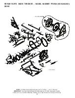
Page 30: ...l Equipment Manufacturer O E M replacement parts Failure to do so could be hazardous damage your snow thrower and void your warranty 9 9 11 11 11 1 2 3 21 5 6 12 13 14 15 20 15 16 17 10 9 8 7 23 19 53 53 53 53 25 26 26 27 39 40 41 42 43 44 32 38 53 53 37 36 35 39 33 28 30 29 31 4 23 24 24 01 02 013 A 18 42 EXPLODED 24 23 24 33 34 22 47 49 50 48 52 51 46 45 4 ...

Page 31: ...RETAINER 16 427542 CONTROL SHAFT 17 402568 CLUTCH ROD 18 169675 RETAINER 19 401732 SHIFTER YOKE 20 402310 PIVOT ROD 21 12000036 RETAINER 22 402878 RETURN SPRING 23 751153 NUT 5 16 18 24 408981 BEARING 25 73930500 NUT 5 16 18 26 198176X479 RUBBER WHEEL PLATE 27 179831 RUBBER RING 28 175344 BEARING 29 178613 WHEEL HUB 30 74760514 SCREW 5 16 18 875 31 12000012 RETAINER RING 32 402187 SPROCKET SHAFT 3...

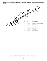
Page 32: ...o so could be hazardous damage your snow thrower and void your warranty 1a 1b 1b 4 3 3 4 5 6 6 7 5 2 01 03 005 B 1 188226 assy of 1a 1b AXLE ASSEMBLY 1a 179352 AXLE SHAFT 1b 9465M ROLL PIN 3 16 2 402691 SPROCKET 3 174697 THRUST WASHER 4 179830 BEARING 5 17490508 BOLT 5 16 18 X 500 6 155443 CLIK PIN 7 189282 SQUARE KEY REPAIR PARTS SNOW THROWER MODEL NUMBER PR6R24 96192002801 DRIVE ...

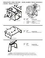
Page 33: ...rer O E M replacement parts Failure to do so could be hazardous damage your snow thrower and void your warranty 421575 COMPLETE LCT ENGINE 1 418694X428 FRAME 2 150406 BOLT 3 8 16 3 428867 SCREW 5 16 18 X 750 REPAIR PARTS SNOW THROWER MODEL NUMBER PR6R24 96192002801 CHASSIS ENGINE PULLEYS 1 2 2 3 3 01 00 034 A 1 01 21 017 B 1 01 01 004 A 1 427963X428 ENGINE MOUNTING PLATE 1 430745 COVER ASSEMBLY ...

Page 34: ...3 B 1 408007 IMPELLER BELT 2 419744 TRACTION BELT 3 423723X479 IDLER ARM BRACKET 4 180523 IDLER PULLEY 5 426589 NUT 5 16 18 6 74780524 SCREW 5 16 18 X 1 50 7 423990X479 IDLER BRACKET 8 428867 SCREW 5 16 18 X 625 9 424297 SHOULDER BOLT 5 16 18 X 500 10 751153 NUT 5 16 18 NYLOCK 11 187786 TRACTION IDLER ARM 12 180522 TRACTION PULLEY 13 74780520 SCREW 5 16 18 X 1 00 14 59289 WASHER 15 73800500 NUT 5 ...

Page 35: ...quipment Manufacturer O E M replacement parts Failure to do so could be hazardous damage your snow thrower and void your warranty REPAIR PARTS SNOW THROWER MODEL NUMBER PR6R24 96192002801 WHEELS KEY PART NO NO DESCRIPTION 1 2 01 06 001 A 1 187831X421 WHEEL ASSEMBLY LH 2 187866X421 WHEEL ASSEMBLY RH ...

Page 36: ...y Original Equipment Manufacturer O E M replacement parts Failure to do so could be hazardous damage your snow thrower and void your warranty 1 2 3 4 5 6 7 01 14 004 B 1 198563 POWER CORD 2 169675 RETAINER PIN 3 180684X008 WRENCH 4 73800600 LOCKNUT 3 8 16 5 19131316 WASHER 3 8 6 192090 SHEAR BOLT 1 4 20 X 1 3 4 7 73800400 LOCKNUT 1 4 20 1 1 2 2 3 2 56 01 14 012 A 4 4 1 180445 SHIFTER ROD TOP 2 187...

Page 37: ...hazardous damage your snow thrower and void your warranty REPAIR PARTS SNOW THROWER MODEL NUMBER PR6R24 96192002801 DECALS 1 181037 DECAL DANGER 3 181035 DECAL DANGER DEFLECTOR 4 181042 DECAL DANGER 6 181033 DECAL INSTRUCTION 7 415390 DECAL AUGER LEVER RT 9 415475 DECAL SPEED CONTROL 11 415391 DECAL TRACTION CLUTCH LEVER 430005 OWNER S MANUAL ENGLISH 430006 OWNER S MANUAL FRENCH 1 3 4 9 7 11 6 1 ...

Page 38: ...38 SERVICE NOTES ...

Page 39: ...39 SERVICE NOTES ...

Page 40: ...is Warranty does not apply to any product which has been sub jected to alteration misuse abuse improper assembly or installation delivery damage or to normal wear of the product 5 Exclusions Excluded from this Warranty are belts shear pins normal wear normal adjustments standard hard ware and normal maintenance 6 In the event you have a claim under this Warranty you must return the product to an a...

Reviews: