background image

30

26

25

58

219

20

219

23

64

208

13

208

11

1

3

2

9

208

208

5

5

207

3

3

3

142

17

29

28

12

51

57

53

52

54

55

145

37

3

37

24

26

25

3

31

24

30

35

3

26

33

10

26

34

35

18

14

38

14

206

212

159

3

115

3

142

211

114

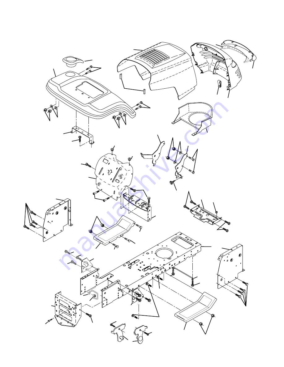
REPAIR PARTS

TRACTOR - - MODEL NUMBER PR1842STC

CHASSIS AND ENCLOSURES

Summary of Contents for 183359

Page 1: ...Always Wear Eye Protection During Operation WARNING Read this Owner s Manual and follow all Warnings and Safety Instructions Failure to do so can result in serious injury IMPORTANT MANUAL Do Not Throw Away 183359 3 15 02 RD Printed in U S A 02478 ...

Page 2: ...facturer s recommendations for wheel weights or counterweights to improve stability Useextracarewithgrasscatchersorotherattachments These can change the stability of the machine Keep all movement on the slopes slow and gradual Do not make sudden changes in speed or direction Avoidstartingorstoppingonaslope Iftireslosetraction disengage the blades and proceed slowly straight down the slope DO NOT D...

Page 3: ...ate of California to cause cancer and birth defects or other reproductive harm Wash hands afterhandling Be sure the area is clear of other people before mowing Stop machine if anyone enters the area Never carry passengers or children even with the blades off Do not mow in reverse unless absolutely necessary Al ways look down and behind before and while backing Never carry children They may fall of...

Page 4: ... will enable you to assemble and maintain your tractor properly Always observe the SAFETY RULES CUSTOMER RESPONSIBILITIES Read and observe the safety rules Followaregularscheduleinmaintaining caringforand using your tractor Follow the instructions under Customer Responsibili ties and Storage sections of this owner s manual WARNING This tractor is equipped with an internal com bustion engine and sh...

Page 5: ...Shaft Steering Sleeve Steering Wheel Steering Wheel Adapter 1 Knob 1 Washer 17 32 x 1 3 16 x 12 Gauge Seat 2 Keys Keys Slope Sheet 2 Mulcher Blades 1 Oil Drain Tube For Future Use 1 Hex Bolt 1 4 28 x 1 1 4 1 Locknut 1 4 28 1 Locknut 1 2 20 CONTENTS OF HARDWARE PACK ...

Page 6: ...m of one hour at 6 10 amps See BATTERY inCUSTOMERRESPONSIBILITIES section of this manual for charging instructions SEAT PAN LABEL TERMINAL TERMINAL STEERING WHEEL INSERT 1 2 HEX NUT STEERING BOOT 1 4 LOCKNUT ADAPTER LOWER STEERING SHAFT EXTENSION SHAFT 1 4 HEX BOLT STEERING WHEEL LARGE FLAT WASHER TABS TAB SLOTS BEFORE REMOVING TRACTOR FROM SKID ATTACH STEERING WHEEL See Fig 1 ASSEMBLE EXTENSION S...

Page 7: ...ake pedal into full BRAKE position and hold Move gearshift lever to 1st gear Slowly release clutch brake pedal and slowly drive tractor off skid Apply brake to stop tractor set parking brake and place gearshift lever in neutral position Turn ignition key to OFF position Continue with the instructions that follow SEAT PAN SHOULDER BOLT ADJUSTMENT KNOB FLAT WASHER SEAT FIG 3 NOTE You may now roll or...

Page 8: ...n and mower blade drive belts in the Service and Adjustments section of this manual Verify that the belts are routed correctly CHECK BRAKE SYSTEM Afteryoulearnhowtooperateyourtractor checktoseethat the brake is properly adjusted See TO ADJUST BRAKE in the Service and Adjustments section of this manual TO INSTALL MULCHER PLATE See Fig 4 NOTE If you installed the mulching blades you will need to ins...

Page 9: ...ARD FAST SLOW ENGINE ON ENGINE OFF OIL PRESSURE LIGHTS ON FUEL CHOKE MOWER HEIGHT PARKING BRAKE LOCKED UNLOCKED REVERSE NEUTRAL HIGH LOW ATTACHMENT CLUTCH ENGAGED MOWER LIFT DANGER KEEP HANDS AND FEET AWAY FREE WHEEL Automatic Models only OVER TEMP LIGHT PARKING BRAKE IGNITION ATTACHMENT CLUTCH DISENGAGED P KEEP AREA CLEAR SLOPE HAZARDS 15 15 15 SEE SAFETY RULES SECTION ...

Page 10: ...the tractor and starting the engine PARKINGBRAKE Locksclutch brakepedalintothebrake position GEARSHIFT LEVER Selects the speed and direction of the tractor ATTACHMENT LIFT LEVER Used to raise lower and adjustthemowerdeckorotherattachmentsmountedtoyour tractor LIFT LEVER PLUNGER Used to release attachment lift lever when changing its position IGNITION SWITCH Used for starting and stopping the engin...

Page 11: ... to OFF position and remove key Always remove key when leaving tractor to prevent unauthorizeduse Never use choke to stop engine IMPORTANT LEAVING THE IGNITION SWITCH IN ANY POSITION OTHER THAN OFF WILL CAUSE THE BATTERY TO BE DISCHARGED DEAD ATTACHMENT CLUTCH LEVER ENGAGED POSITION IGNITION KEY DISENGAGED POSITION PARKING BRAKE ENGAGED POSITION GEAR SHIFT LEVER THROTTLE CHOKE CONTROL LEVER BRAKE ...

Page 12: ...th mower in desired height of cut position gauge wheels should be assembled so they are slightly off the ground Install gauge wheel in appropriate hole with shoulderbolt 3 8washer and3 8 16locknutandtighten securely Repeatforoppositesideinstallinggaugewheelinsame adjustmenthole TO TRANSPORT Raiseattachmentlifttohighestpositionwithattachment lift control When pushing or towing your tractor be sure ...

Page 13: ... performance See TO ADJUST CARBURETOR in the Service and Adjustments section of this manual ADD GASOLINE Fill fuel tank to bottom of filler neck Do not overfill Use fresh clean regularunleadedgasolinewithaminimum of 87 octane Use of leaded gasoline will increase carbon and lead oxide deposits and reduce valve life Do not mix oil with gasoline Purchase fuel in quantities thatcanbeusedwithin30daysto...

Page 14: ...willsuittheterrainandgivebestperformanceofthe attachment being used MULCHING MOWING TIPS IMPORTANT FOR BEST PERFORMANCE KEEP MOWER HOUSING FREE OF BUILT UP GRASS AND TRASH CLEAN AFTER EACH USE Thespecialmulchingbladewillrecutthegrassclippings many times and reduce them in size so that as they fall ontothelawntheywilldisperseintothegrassandnotbe noticed Also the mulched grass will biodegrade quickl...

Page 15: ...ut oil filter 1 2 GENERAL RECOMMENDATIONS The warranty on this tractor does not cover items that have beensubjectedtooperatorabuseornegligence Toreceive full value from the warranty operator must maintain tractor as instructed in this manual Some adjustments will need to be made periodically to properly maintain your tractor All adjustments in the Service and Adjustments section of this manual sho...

Page 16: ...ntheengineisrunningandtheattachmentclutchis engaged any attempt by the operator to leave the seat should shut off the engine Theattachmentclutchshouldneveroperateunlessthe operator is in the seat BLADE CARE Forbestresultsmowerbladesmustbekeptsharp Replace bent or damaged blades 5 8 BOLT OR PIN BLADE CENTER HOLE TO SHARPEN BLADE See Fig 12 NOTE Wedonotrecommendsharpeningblade butifyou do be sure th...

Page 17: ...ERY in the Service and Adjustment section of this manual CLOSED AND LOCKED POSITION DRAIN TUBE OIL DRAIN VALVE TO CHANGE ENGINE OIL See Figs 13 and 14 Determine temperature range expected before oil change All oil must meet API service classification SF SJ Be sure tractor is on level surface Oil will drain more freely when warm Catch oil in a suitable container Remove oil fill cap dipstick Be care...

Page 18: ... at the beginning of each mowing season or after every 100 hours of use whichever comes first Spark plug type and gap setting is shown in PROD UCT SPECIFICATIONS section of this manual ENGINE OIL FILTER Replace the engine oil filter every season or every other oil changeifthetractorisusedmorethan100hoursinoneyear FIG 15 FUEL FILTER CLAMP CLAMP IN LINE FUEL FILTER See Fig 15 The fuel filter should ...

Page 19: ... ATTACHMENT OTHER THAN THE MOWER DECK IS TO BE MOUNTED ON THE TRAC TOR REMOVE THE FRONT LINKS AND HOOK THE CLUTCH SPRING INTO SQUARE HOLE IN FRAME TO INSTALL MOWER See Fig 16 Raise attachment lift lever to its highest position Slide mower under tractor with deflector shield to right side of tractor Lower lift lever to its lowest position Connect front links to mower deck and secure with retainersp...

Page 20: ...TRUNNION D D FIG 19 NUT F FRONT LINKS MANDREL TO LEVEL MOWER HOUSING Adjust the mower while tractor is parked on level ground or driveway Makesuretiresareproperlyinflated See PROD UCTSPECIFICATIONS sectionofthismanual Iftiresare over or underinflated you will not properly adjust your mower SIDE TO SIDE ADJUSTMENT See Figs 17 and 18 Raise mower to its highest position At the midpoint of both sides ...

Page 21: ...on the gear shift lever in the neutral N position Tighten adjustment bolt securely NOTE Ifadditionalclearanceisneededtogettoadjustment bolt move mower deck height to the lowest position ADJUSTMENT BOLT NEUTRAL LOCK GATE GEARSHIFT LEVER FIG 24 TO REPLACE MOTION DRIVE BELT See Fig 23 Parkthetractoronlevelsurface Engageparkingbrake For assistance thereisabeltinstallationguidedecalonbottom side of lef...

Page 22: ... sparking from acciden tal grounding Lift seat pan to raised position DisconnectBLACKbatterycablefirstthenREDbattery cable and carefully remove battery from tractor Installnewbatterywithterminalsinsamepositionasold battery First connect RED battery cable to positive terminal with hex bolt and keps nut as shown Tighten securely Slide terminal cover over terminal ConnectBLACKgroundingcabletonegative...

Page 23: ...HEX BOLT POSITIVE RED CABLE NEGATIVE BLACK CABLE TERMINAL COVER ENGINE TO ADJUST THROTTLE CONTROL CABLE The throttle control has been preset at the factory and adjustment should not be necessary Check adjustment as described below before loosening cable If adjustment is necessary see engine manual TO ADJUST CARBURETOR The carburetor has been preset at the factory and adjust mentshouldnotbenecessar...

Page 24: ...NG IN ESSENTIAL FUEL SYSTEM PARTS SUCH AS CARBURETOR FUEL FILTER FUEL HOSE OR TANK DURING STORAGE ALSO EXPERIENCE INDICATES THAT ALCOHOL BLENDED FUELS CALLED GASOHOL OR USING ETHANOL OR METHANOL CAN ATTRACT MOISTURE WHICH LEADS TO SEPARATION AND FORMATION OF ACIDS DURING STORAGE ACIDIC GAS CAN DAMAGE THE FUEL SYSTEM OF AN ENGINE WHILE IN STORAGE Drain the fuel tank Start the engine and let it run ...

Page 25: ...lty ignition switch 7 Check replace ignition switch 8 Faulty solenoid or starter 8 Check replace solenoid or starter 9 Faulty operator presence switch es 9 Contact an authorized service center department Engine clicks but will not 1 Weak or dead battery 1 Recharge or replace battery start 2 Corroded battery terminals 2 Clean battery terminals 3 Loose or damaged wiring 3 Check all wiring 4 Faulty s...

Page 26: ... Mower deck not level 4 Level mower deck 5 Low uneven tire air pressure 5 Check tires for proper air pressure 6 Worn bent or loose blade 6 Replace sharpen blade Tighten blade bolt 7 Buildup of grass leaves and trash under mower 7 Clean underside of mower housing 8 Mower drive belt worn 8 Replace mower drive belt 9 Blades improperly installed 9 Reinstall blades sharp edge down 10 Improper blades us...

Page 27: ...UR TRACTOR IS EQUIPPED WITH A SPECIAL ALTERNATOR SYSTEM THE LIGHTS ARE NOT CONNECTED TO THE BATTERY BUT HAVE THEIR OWN ELECTRICAL SOURCE BECAUSE OF THIS THE BRIGHTNESS OF THE LIGHTS WILL CHANGE WITH ENGINE SPEED AT IDLE THE LIGHTS WILL DIM AS THE ENGINE IS SPEEDED UP THE LIGHTS WILL BECOME THEIR BRIGHTEST WIRING INSULATED CLIPS NOTE IF WIRING INSULATED CLIPS WERE REMOVED FOR SERVICING OF UNIT THEY...

Page 28: ...28 REPAIR PARTS TRACTOR MODEL NUMBER PR1842STC ELECTRICAL 28 29 26 24 42 43 27 27 25 41 27 27 40 33 90 30 8 2 1 27 D C AMPERES 45 16 22 21 52 16 ...

Page 29: ...58 Fuse 27 73510400 Nut Keps Hex 1 4 20 Unc 28 4207J Cable Ground 6ga 12 black 29 121305X Switch Plunger Nc Gray 30 175566 Switch Ign 33 140401 Key Ign Molded Generic 40 179720 HarnessIgn 41 71110408 Bolt Fin Hex 1 4 20uncx 1 2 42 131563 CoverTerminalRed 43 178861 Solenoid 45 121433X AmmeterRectangular 52 141940 ProtectionLoop 90 180449 CoverTerminal NOTE All component dimensions given in U S inch...

Page 30: ... 208 11 1 3 2 9 208 208 5 5 207 3 3 3 142 17 29 28 12 51 57 53 52 54 55 145 37 3 37 24 26 25 3 31 24 30 35 3 26 33 10 26 34 35 18 14 38 14 206 212 159 3 115 3 142 211 114 REPAIR PARTS TRACTOR MODEL NUMBER PR1842STC CHASSIS AND ENCLOSURES ...

Page 31: ...SupportFender 33 179716X428 Footrest Pnt Lh 34 179717X428 Footrest Pnt Rh 35 72110606 Bolt Rdhd Sht Sqnk 3 8 16 x 3 4 37 17490508 Screw Thdrol 6 16 18 x 1 2 TYT 38 175710 Bracket Asm Pivot Mower Rear 51 73800400 Nut Lock Hex W Ins 1 4 20 52 19091416 Washer 9 32 x 7 8 x 16 Ga 53 144697 Bracjet Grukke Lh 54 161464 Screw Hex Wshd 8 18 x 7 8 55 144696 Bracket Grille Rh 57 74780412 Bolt Hex 1 4 20 x 3 ...

Page 32: ...12 55 77 61 22 27 26 6 113 18 51 5 18 6 85 52 30 32 32 30 52 11 85 80 4 3 13 81 84 82 64 65 145 79 16 96 26 27 51 48 150 151 202 49 47 50 120 21 8 10 156 165 168 166 163 14 159 161 198 158 164 83 162 169 89 197 6 170 66 56 63 116 70 69 26 REPAIR PARTS TRACTOR MODEL NUMBER PR1842STC DRIVE ...

Page 33: ...620 Screw 3 8 16 x 1 1 4 57 130801 V Belt Ground Drive 95 25 59 169691 Keeper Belt Span Ctr 61 17120614 Screw 3 8 16 x 875 62 8883R Cover Pedal Blk Round 63 175410 Engine Pulley 64 71170764 Bolt Hex 65 10040700 Washer Lock Hvy Hlcl Spr 7 16 66 154778 Keeper Belt Engine Foolproof 69 142432 Screw Hex wsh HiLo 1 4 x 1 2 unc 70 134683 Guide Belt Mower Drive RH 74 137057 Spacer Axle 75 121749X Washer 2...

Page 34: ... 3 43 6 43 8 10 40 32 11 8 6 87 46 46 8 6 87 29 88 71 17 43 91 2 1 41 42 37 36 37 38 12 39 44 51 54 33 35 34 68 67 67 67 13 65 68 15 15 15 29 29 82 REPAIR PARTS TRACTOR MODEL NUMBER PR1842STC STEERING ASSEMBLY ...

Page 35: ...Ga 34 10040500 Washer Lock Hvy Hlcl Spr 5 16 35 73540500 CrownlockNut5 16 24 36 155099 Bushing Strg 37 152927 Screw 38 180657 Insert Cap Strg Wh Au 39 19182411 Washer 9 16 ID x 1 1 2 OD 11 Ga 40 7810H Lock nut 41 159945 Adaptor Wheel Strg 42 145054X428 Boot Steering Dash 43 121749X Washer 25 32 X 1 1 4 X 16 Ga 44 180640 Extension Steering Shaft LR LT 46 121232X Cap Spindle Fr Top Blk 51 73540400 N...

Page 36: ...at 11 166369 Knob Seat 12 121246X Bracket Mounting Switch 13 121248X Bushing Snap Blk Nyl 50 Id 14 72050412 Bolt Rdhd Sqnk 1 4 20x1 1 2 15 134300 Spacer Split 28x 88 16 121250X SpringCprsn 17 123976X Nut Lock 1 4 Lge Flg Gr 5 Zinc 21 171852 Bolt Shoulder 5 16 18 Unc 22 73800500 Nut Hex Lock W Ins 5 16 18 24 19171912 Washer 17 32 X 1 3 16 X 12 Ga 25 127018X Bolt Shoulder 5 16 18 X 62 KEY PART NO NO...

Page 37: ...R Ts 20x10 8 C Service 10 7152J Tube Rear Service Item Only 11 104757X421 Cap Axle 1 50 X 1 00 144334 Sealant Tire 10 oz Tube 8 20 14 5 1 156369 DecalOper 2 176305 Decal Fender Side 3 176308 Decal Hood LH 4 182005 Decal Side Panel Logo 5 181564 Decal HP Engine 6 179128 Decal Deck B 42 8 170563 DecalWarningMult Language 9 172740 DecalFenderLogo 10 157140 Decal Fender Danger E F 1 2 2 11 19 11 17274...

Page 38: ...38 2 1 OPTIONAL EQUIPMENT Spark Arrester 29 44 46 32 31 33 37 33 62 13 4 72 78 81 3 16 78 23 45 14 38 40 41 112 REPAIR PARTS TRACTOR MODEL NUMBER PR1842STC ENGINE ...

Page 39: ...ooth 3 8 23 169837 ShieldBrn DbrGuard 29 137180 Kit Spark Arrestor Flat Scrn 31 180645 Tank Fuel Front 32 140527 Cap Asm Fuel W sym Vented 33 123487X Clamp Hose Black 37 137040 Line Fuel 20 38 148315 Plug Drain Oil Easy 40 124028X Bushing Snap Nyl Blk Fuel Line 41 139277 Stem Tank Fuel 44 17670412 ScrewHexwshThdrol1 4 20x3 4 45 17000612 Screw Hexwsh Thdr 3 8 16 x 3 4 46 19091416 Washer 9 32 X 7 8 ...

Page 40: ...144 147 147 142 149 142 49 50 51 54 52 53 55 56 34 1 46 44 21 24 25 26 27 2 28 29 23 21 21 21 18 18 20 2 48 59 19 4 3 5 6 21 40 143 36 40 37 40 159 152 151 153 154 157 158 67 153 156 155 132 91 94 182 95 183 132 113 117 116 118 119 114 115 112 114 117 119 116 115 111 118 113 102 102 104 103 105 106 104 105 106 103 101 ...

Page 41: ...asher Hardened 55 155046 Arm Idler 56 122052X Spacer Retainer 59 173442 Guard TUV Idler 67 171598 Knob 68 144959 V Belt 42 Mower 91 180532 Bracket Asm Noseroller LH 94 132264 Roller Nose 95 180533 Bracket Asm Noseroller RH 101 136420 MulcherCover 102 71081010 Screw 103 19061216 Washer Flat 104 10071000 Washer Lock 105 160793 Latch Assembly 106 2029J Nut Weld 111 179292X421 Bracket Gauge Wheel LH 1...

Page 42: ...42 36 15 20 16 1718 20 20 15 20 4 5 6 2 3 1 6 5 4 7 8 37 41 40 38 12 11 31 32 31 32 19 19 13 13 13 13 REPAIR PARTS TRACTOR MODEL NUMBER PR1842STC MOWER LIFT ...

Page 43: ...866 Link Lift RH Fixed Length 13 4939M RetainerSpring 15 173288 Link Front 16 73350800 Nut Jam Hex 1 2 13 Unc 17 175689 Trunnion 18 73800800 Nut Lock w Wsh 1 2 13 Unc 19 139868 Arm Suspension Rear 20 163552 RetainerSpring 31 169865 Bearing Pvt Lift 32 73540600 Nut Crownlock 3 8 24 36 155097 Pointer Height Indicator 37 123935X Plug Hole Blk 1 485 1 515 Dia 38 17060516 Screw Thdrol 5 16 18 x 1 40 19...

Page 44: ...44 NOTES ...

Page 45: ...ed for rental or commercial purposes is limited to 90 days from the date of original purchase 5 This Warranty applies only to products which have been properly assembled adjusted operated and main tained in accordance with the instructions furnished This Warranty does not apply to any product which has been subjected to alteration misuse abuse improper assembly or installation delivery damage or t...

Page 46: ...Power Train Component and parts The cost of normal maintenance and replacement of service items which are not defective shall be paid for by the original purchaser C SecuringWarrantyService Warranty service can be arranged for by contacting either a Tecumseh Authorized Service Outlet any Tecumseh Registered Service Dealer Tecumseh Authorized Service Distributor or Tecumseh Central Warehouse Distri...

Page 47: ...the face Do not mow slopes greater than 15 degrees Make turns gradually to prevent tipping or loss of control Exercise extreme caution when changing direction on slopes 1 Fold this page along dotted line indicated above 2 Hold page before you so that its left edge is vertically parallel to a tree trunk or other upright structure 3 Sight across the fold in the direction of hill slope you want to me...

Page 48: ... for Trimmers Brushcutters and Blowers 3 For replacement parts have available the following information a Model Number Manufacturer s I D Number b Description of part NOTE Electrolux Home Products provides parts and service through its authorized distribu tors and dealers therefore all requests for parts and service should be directed to your local dealer s The philosophy of Electrolux Home Produc...

Reviews: