12
CUSTOMER RESPONSIBILITIES
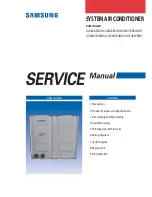
OIL FILLER PLUG
OIL LEVEL
OIL
DRAIN
PLUG
FIG. 16
Disconnect spark plug wire before performing any maintenance (except carburetor adjustment) to
prevent accidental starting of engine.
Prevent fires! Keep the engine free of grass, leaves, spilled oil, or fuel. Remove fuel from tank before
tipping unit for maintenance. Clean muffler area of all grass, dirt, and debris.
Do not touch hot muffler or cylinder fins as contact may cause burns.
FIG. 17
TO CHANGE ENGINE OIL (See Figs. 16 and 17)
Determine temperature range expected before oil change.
All oil must meet API service classification SF-SJ.
•
Be sure tiller is on level surface.
•
Oil will drain more freely when warm.
•
Use a funnel to prevent oil spill on tiller, and catch oil in
a suitable container.
•
Remove drain plug. For easier removal of plug use
7/16 12 Pt. socket with extension.)
•
Tip tiller forward to drain oil.
•
After oil has drained completely, replace oil drain plug
and tighten securely.
•
Remove oil filler plug. Be careful not to allow dirt to enter
the engine.
•
Refill engine with oil. See “CHECK ENGINE OIL LEVEL”
in the Operation section of this manual.
ENGINE
LUBRICATION
Use only high quality detergent oil rated with API service
classification SF-SJ. Select the oil’s SAE viscosity grade
according to your expected temperature.
NOTE:
Although multi-viscosity oils (5W-30, 10W-30, etc.)
improve starting in cold weather, these multi-viscosity oils
will result in increased oil consumption when used above
40°F (4°C). Check your engine oil level more frequently to
avoid possible engine damage from running low on oil.
Change the oil after every 25 hours of operation or at least
once a year if the tiller is not used for 25 hours in one year.
Check the crankcase oil level before starting the engine and
after each five (5) hours of continuous use. Add SAE 30
motor oil or equivalent. Tighten oil filler plug securely each
time you check the oil level.
TEMPERATURE RANGE ANTICIPATED BEFORE NEXT OIL CHANGE
SAE VISCOSITY GRADES
-20
°
0
°
30
°
40
°
80
°
100
°
-30
°
-20
°
4
°
20
°
30
°
40
°
°
F
°
C
-10
°
10
°
60
°
10W-30 / 5W-30
SAE 30
FIG. 18
COVER
KNOB
BASE
FOAM
PRECLEANER
COVER
AIR FILTER (See Fig. 18)
Your engine will not run properly using a dirty air filter. Clean
the foam pre-cleaner after every 25 hours of operation or
every season. Service paper cartridge every 100 hours of
operation or every season, whichever occurs first.
Service air cleaner more often under dusty conditions.
•
Remove cover screw and cover.
TO SERVICE PRE-CLEANER
•
Remove foam pre-cleaner from air cleaner cover.
•
Wash it in liquid detergent and water.
•
Squeeze it dry in a clean cloth.
•
If very dirty or damaged, replace pre-cleaner.
•
Reinstall pre-cleaner into air cleaner cover.
•
Reinstall cover and secure screw.
TO SERVICE CARTRIDGE
•
Carefully remove cartridge to prevent debris from enter-
ing carburetor. Clean base carefully to prevent debris
from entering carburetor.
•
Clean cartridge by tapping gently on flat surface. If very
dirty or damaged, replace cartridge.
•
Reinstall cartridge, cover with pre-cleaner and secure
with screw.
IMPORTANT:
PETROLEUM SOLVENTS, SUCH AS
KEROSENE, ARE NOT TO BE USED TO CLEAN THE
CARTRIDGE. THEY MAY CAUSE DETERIORATION OF
THE CARTRIDGE. DO NOT OIL CARTRIDGE. DO NOT
U S E P R E S S U R I Z E D A I R T O C L E A N O R D R Y
CARTRIDGE.
AIR CLEANER
CARTRIDGE
COOLING SYSTEM (See Fig. 19)
Your engine is air cooled. For proper engine performance
and long life keep your engine clean.
•
Clean air screen frequently using a stiff-bristled brush.
•
Keep cylinder fins, levers, and linkage free of dirt and
chaff.
Summary of Contents for 175680
Page 26: ...26 SERVICE NOTES...