background image

Fault Finding - Page 22

SYMPTOM

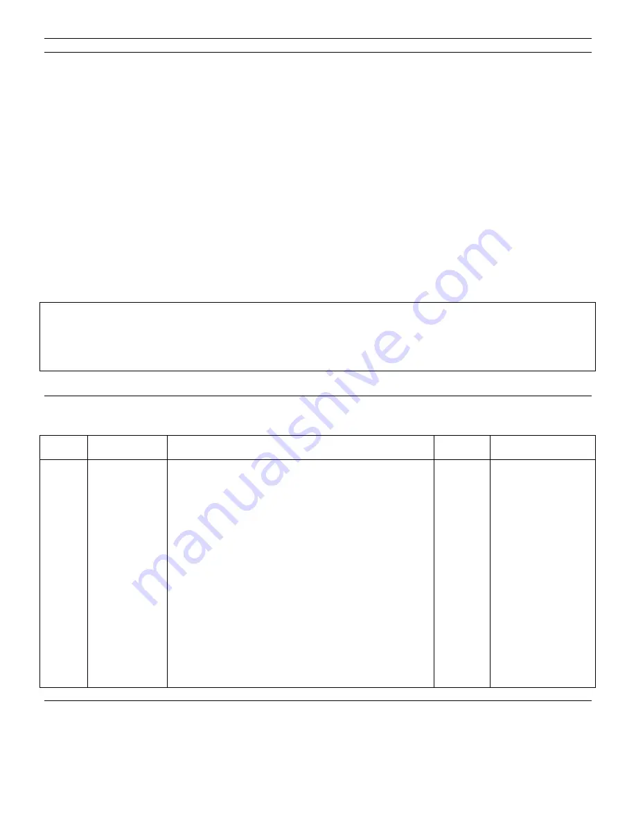
UNEXPLAINED SHUT-DOWN OF THE APPLIANCE

This appliance contains an Energy Cut-Off Device which reacts the water in the heat exchanger exceeds the anticipated
temperature limit. Although it is intended to guard against failure of the automatic gas valve, it may be triggered inadvertently
by other causes, especially during the summer months when the inlet water temperature is unusually high.

POSSIBLE CAUSE

SOLUTION

Failure of the appliance thermostat.

Repair or replace.

However, if the energy cut-off device reacts to a slowly closing automatic gas valve, the shut down of the appliance may be
accompanied by noises from the heat exchanger and pipework. The pressure relief valve located on top of the water
governor may also have vented water into the case. In this situation it is possible that STEAM will come out of the hot water
tap when turned on.

POSSIBLE CAUSE

SOLUTION

Excessive resistance of push rod.

Exchange push rod and seals. Lubricate with Dow Corning III
silicone grease and ensure free movement.

IMPORTANT NOTE

To ensure continued safe operation, we recommend that if the pressure relief valve has operated, it should be

replaced immediately

8. SHORT SPARE PARTS LIST - Page 22

Key No

G.C. Part No.

Description.

No. Off.

Makers Part No.

1

284 957

Seal Pack - Chassis to Flue Terminal

1

31/1 2299

11

285 907

Case Assembly

1

10/17543

14

285 910

Case Seal - Self Adhesive Rubber

1

10/1 7501

12

285 908

Viewing Aperture Seal

1

1 0/1 7499

13

285 909

Viewing Aperture Glass

1

10/17500

40

285 513

InjectorN.G.1.2mm

14

19/12196

43

285 678

Flame Safety Device Assembly

1

10/13477

54

285 930

Thermocouple - Special

1

10/17461

53

285 929

Thermocouple Connection - Special

1

10/1 7790

52

397 688

Interrupter Insert

1

10/1 3846

55

285 931

Electrode Assembly

1

10/1 7493

58

285 679

Pilot Injector - Special

1

19/1 2690

44

393 492

PiezoUnit-RV1174

1

10/11935

59

285 934

Igniter ‘IGN’ Button

1

10/1 7507

60

285 935

Starter ‘ON’ Button Assembly

1

10/17540

61

285 936

Stop ‘OFF’ Button Assembly

1

10/1 7541

83

285 944

Diaphragm Assembly

1

10/1 7534

114

285 691

Thermostat Assembly

1

10/13486

62

285 937

Energy Cut-Off Device Assembly - Includes Grommets

1

10/1 7792

78

285 942

Pressure Relief Valve Assembly

1

10/17866

Summary of Contents for Main Thames

Page 1: ... to install appliances correctly could lead to prosecution Installation must be in accordance with the Building Regulations Byelaws of the Water Undertaking and LE I Regulations It should be in accordance also with any relevant requirements of the Local Gas Region and Local and the relevant recommendations of the following British Standard Codes of practice BS 6891 BS 5440 1 2 and BS 5546 LEAVE TH...

Page 2: ...om or space in which it is installed Where this appliance is installed in a compartment air vents to the compartment at both high and low levels should be provided for cooling Further guidance is given in BS 5440 Pt 2 Position of Air Vent High Low In compartment which is ventilated to room 274 cm 274 cm 42 in 42 in2 In compartment which is ventilated to outside 137 cm 137 cm 21 in 21 in GENERAL IM...

Page 3: ...6in Part No 31 10321 150mm 230mm 6in 9in Part No 31 10322 230mm 380mm 9in 15in Part No 31 10323 380mm 610mm 15in 24in Part No 31 1 0324 Flue Terminal Guard Optional Part No 10 10262 Notes Additional external pipework and fittings may affect the resistance and must be taken into account on installation The nominal burner pressure should be 12 5 mbar and will only be obtained if the appliance inlet ...

Page 4: ...d with the terminal pack NOTE Where the appliance is to be installed into a SEDUCT the minimum duct required is 228mm 9in deep 349mm 15 in wide 3 Where the building regulations require it a flue terminal guard should be fitted symmetrically around the outer part of the flue terminal 4 Unpack the water heater Find the bags of accessories before discarding the packaging Fig 3 5 Turn the temperature ...

Page 5: ... length is in excess of 3 metres 10ft then the use of 22mm copper pipe is necessary 1 Assemble the filter O ring and inlet tail to the gas inlet 2 Depending on whether the main supply pipe is to be routed vertically or horizontally to the appliance connect the gas service cock stamped G either directly to the gas inlet tail or within the supply pipe NOTE The service cock should be as close to the ...

Page 6: ...supply is turned OFF IMPORTANT When routing the supply pipe to the appliance ensure that it can be lowered by approx 25mm to allow for disconnection when servicing 4 Connect the hot water supply pipes to the water outlet 15mm compression 5 Turn ON the mains water supply turn ON the water service cock and open all the hot water outlets to allow water to flow Purge the air from the system by closing...

Page 7: ... 4 Remove the screw and sealing ring from the burner pressure test point and attach a pressure gauge Fig 10 5 Fully depress and hold the ON button and repeatedly press and release the IGN button until the pilot is lit The pilot flame can be observed through the pilot viewing window 6 Hold the ON button in for a further 10 seconds after the pilot is lit then release If the pilot goes out repeat the...

Page 8: ...liance see the Instructions for Use booklet Show the user the position of the Identification Badge HAND OVER THE INSTRUCTIONS FOR USE TO THE USER LEAVE THESE INSTALLATION AND SERVICE INSTRUCTIONS WITH THE USER FOR USE ON FUTURE CALLS ADVISE THE USER THAT FOR CONTINUED EFFICIENT AND SAFE OPERATION OF THE APPLIANCE IT IS IMPORTANT THAT SERVICING IS CARRIED OUT AT INTERVALS RECOMMENDED BY THE LOCAL B...

Page 9: ...WARNING NEVER OPERATE THIS APPLIANCE WITH THE OUTER CASE REMOVED Fig 14 1 Check the piezo unit flame safety device and thermocouple clean or replace if necessary 2 Remove the burner assembly and clean using a soft brush or vacuum cleaner 3 Check the pilot injector and clean or replace if necessary Also clean the lint filter 4 Remove the water governor assembly complete with push rod Replace the se...

Page 10: ...DER UNLESS OTHERWISE STATED This chart shows the steps to be taken in order access a specific part or perform a particular function Use this chart in conjunction with the detailed procedures on the following pages START General Access Main Burner Remove Piezo Unit Remove Pilot Injector Remove Thermocouple and Electrode Remove Pilot Injector Remove Water Governor and Push Rod Remove Energy Cut Off ...

Page 11: ...IN BURNER a Turn OFF the gas and water supplies at the service cocks b Slide out the bottom cover c Remove the 3 fixing screws and pull off the outer case Fig 18 d Remove 4 fixing screws from the burner assembly 2 each side e Remove 2 screws securing the front to the heating unit f Pull the burner assembly slightly forwards to clear the injectors then pull apart and withdraw taking care not to sna...

Page 12: ...lint filter disconnect the union nut and carefully lift up the pilot tube taking care not to lose the pilot injector c On re assembly ensure the pilot injector is correctly seated taper side downwards and that the lint filter is correctly assembled and located on the union nut NOTE The lint filter can be cleaned if required Fig 22 6 5 FLAME SAFETY DEVICE a Gain general access see 6 2 b Disengage t...

Page 13: ... the water service cock is in the ON position Fig 23 6 6 TO DRAIN THE APPLIANCE a Ensure that the gas and water service cocks are turned OFF b Open a hot water outlet c Have a suitable container to hand Remove the drain screw from the water service cock and allow the water to drain Fig 24 6 7 WATER GOVERNOR a Gain general access see 6 2 b Drain the appliance see 6 6 c Release the inlet water conne...

Page 14: ...e brass washer and 0 ring from the top opening Clean the washer I Clean the top opening then pack with a silicone grease such as Dow Corning 111 Fit a new 0 ring and re fit the brass washer m Hold the thrust plate remove the fixing nut and lift out the diaphragm assembly Clean or renew as required On re assembly tighten the fixing nut finger tight plus a turn only n Check and if necessary replace ...

Page 15: ...ock is in the OFF position this will ensure that water CANNOT flow and open the automatic valve Turn ON the gas purge and light the pilot this will pressurise the burner supply pipe Test the burner supply pipe joints for gas soundness using leak detection fluid j Re assemble remaining parts and ensure the water service cock is in the ON position IMPORTANT If the automatic valve and burner manifold...

Page 16: ...assembly the temperature selector spindle will disconnect itself from the throttle body On re assembly the rod must be positioned before the throttle is secured in place g Remove the 2 screws securing the throttle to the chassis base then remove the throttle WARNING Keep the throttle body pointing away from your face and body when you turn the screw The spring adjuster spring and gland housing wil...

Page 17: ... SPLASH ONTO SKIN OR INTO THE EYES WASH ANY AFFECTED AREAS WITH LARGE AMOUNTS OF COLD WATER AND SEEK MEDICAL ADVICE CARRY OUT THE FOLLOWING OPERATION OUT OF DOORS ACID WATER SOLUTION CAN DAMAGE FURNISHINGS ETC a Gain general access see 6 2 b Drain the appliance see 6 6 c Remove the heating unit see 6 11 d Invert the heating unit on a suitable bench or table e Using a suitable bung close off the th...

Page 18: ...and seal to the outer case by bending over the 2 spare straight tabs Fig 38 6 14 ENERGY CUT OFF DEVICE a Gain general access see 6 2 b Disconnect the energy cut off leads from the interrupter located on the underside of the chassis c Remove the 2 screws securing the energy cut off device to the heating unit located top front left d Pull the leads complete with grommets up through the chassis base ...

Page 19: ...th pilot injector Part No 19 12690 Also clean the lint filter located at the base of pilot tube 8 Faulty components 8 Replace any faulty components found Piezo Unit Part No 10 11935 Electrode Assembly Part No 10 17493 9 No gas to the appliance 9 Call in your local British Gas Region PILOT LIGHTS BUT WILL NOT REMAIN ALIGHT 1 Thermocouple connections loose 1 Tighten the connections 2 Pilot flame sof...

Page 20: ...anti clockwise from the fully in position When correct the burner ignition should be smooth and quiet when a hot water outlet is opened 6 Thermostat throttle stuck in the open position Will also cause a high water rate 6 Descale regrease and replace O rings as necessary NO OR LOW WATER FLOW RATE 1 Blocked water filter 1 Clean the debris from the filter 2 Heat exchanger blocked with lime 2 Descale ...

Page 21: ...0 rings as necessary NOISY HEATER 1 Heat exchanger scaled Ultimately this will cause the heat exchanger fins to discolour and buckle 1 Descale or replace Part No 10 17667 2 Noisy ignition could be caused by incorrect setting of the slow ignition screw 2 See Fig 16 for the position of the screw Turning the screw clockwise delays the ignition anti clockwise advances the ignition The screw should be ...

Page 22: ...ase and ensure free movement IMPORTANT NOTE To ensure continued safe operation we recommend that if the pressure relief valve has operated it should be replaced immediately 8 SHORT SPARE PARTS LIST Page 22 Key No G C Part No Description No Off Makers Part No 1 284 957 Seal Pack Chassis to Flue Terminal 1 31 1 2299 11 285 907 Case Assembly 1 10 17543 14 285 910 Case Seal Self Adhesive Rubber 1 10 1...

Page 23: ...Short Spare Parts List Page 23 Back Page ...

Reviews: