Potterton Envoy Flowsure Installation & Service Instructions Manual Download Page 18

Commissioning

Publication No. 559779

18

Commissioning – Page 18

Final Assembly

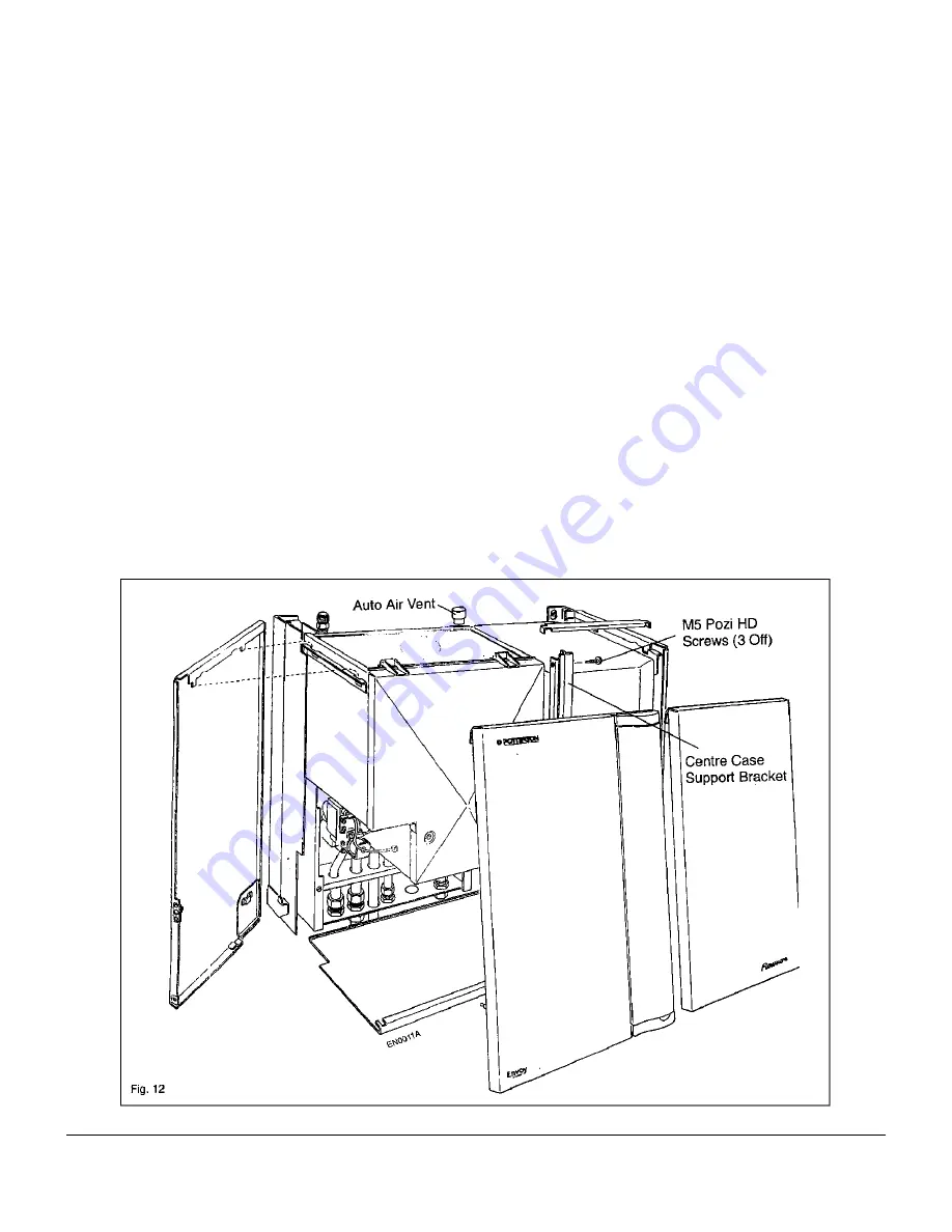
Remove the three M5 pozi head screws from the right hand
side of the boiler as shown, Secure the centre case support
bracket using the three screws previously removed. Attach
casing side panels onto the boiler as illustrated (Fig. 12)
ensuring that the three lugs on each panel are correctly
located. Slide in the bottom panel and push fully home.
Engage hooks on the top rear of the front panel into the  slot in
the top front corner of each side panel. Lower the front panel
to engage brass studs into the retaining clips, press fully home
to lock panel into position.

External Controls

Check that any other external control connected in the
system, such as timers and thermostats, control the boiler
as required.

User's Instructions

A User's Guide is provided with this boiler but the
householder must have the operation of the boiler and
system explained by the installer. The householder must
also be advised of the importance of annual servicing and
of the precautions necessary to prevent damage to the
system and building, in the event of the system remaining
out of commission in frost conditions.

Information must also be passed to the customer on the
type of corrosion inhibitor that has been added to the
system and of the need to maintain the correct
concentration levels as recommended by the
manufacturer.

Summary of Contents for Envoy Flowsure

Page 1: ... gas appliances are installed by competent persons in accordance with the above regulations Failure to install appliances correctly could lead to prosecution The polythene bags used for packaging are a potential hazard to babies and young children and MUST BE DISPOSED OF IMMEDIATELY Installation must be in accordance with the Installation Service Instructions and the rules in force LEAVE THESE INS...

Page 2: ...orage Tanks The flue system is room sealed and fan powered The combination boilers which are designed to provide domestic hot water and or central heating must be used on FULLY PUMPED sealed systems only The combination boiler will adjust automatically to provide central heating outputs between 23 45 kW and 14 8 kW to suit the system requirements Domestic hot water has priority over the central he...

Page 3: ...________________ Igniter Norton 401S Hot Surface Flame Detector Morgon Matroc Storage Tank Details 50 Litre Gas Control Valve SIT Nova Mix 1 8 Air Gas Ratio Packed Weight 20kg Electrical Supply 230V 50Hz Full Weight 65kg Fuse Rating External 3A Packed Weight Boiler 52kg Max Cold Water Gas Supply Connections 15mm Compression Supply Pressure 10 bar Flow Connections 22mm Compression Normal Secondary ...

Page 4: ...Technical Data Publication No 559779 4 Technical Data Page 4 Fig 2 ...

Page 5: ...ns Model Water Bye Laws Building Regulations Building Standards for Scotland Health and Safety Document No 635 The Electricity at Work Regulations 1989 Health and Safety Information for the Installer and Service Engineer Under the Consumer Protection Act 1987 and Section 6 of the Health and Safety at Work Act 1974 we are required to provide information on substances hazardous to health Small quant...

Page 6: ...lled in a timber framed building it should be fitted in accordance with the British Gas publication Part 19 Building and Kitchen Work If in doubt advice must be sought from the local region of British Gas or from Potterton Myson Clearances around the Boiler and Tank The following minimum clearances must be maintained after installation for correct operation and servicing of the boiler and tank Fro...

Page 7: ...to be re entering any building the appliance MUST be turned OFF IMMEDIATELY G A A B C B C C E F G G G G K L L K K F F EN0006A Horizontal Flues Vertical Flues Flue Terminals Facing Terminal or Wall A P R Q Q S N N N H I Fig 3 Terminal position Minimum spacing A Directly below an openable window air vent or any other ventilation opening 300 mm B Below gutters soil pipes or drain pipes 75 mm C Below ...

Page 8: ...es a by pass should be fitted as far away from the boiler as possible Drain off taps should be fitted in the pipework close to the boiler and at all low points of the system Note Although the system can be emptied using the drain off taps installed in the pipework around the system to empty the boiler it is necessary to remove the drain off cap positioned within the boiler case Installation The in...

Page 9: ...ing a cistern pressure booster pump and if necessary an automatic pressure reducing valve or flow restrictor The pressure booster pump must be capable of pressurising the system to a minimum of 1 0 bar 14 p s i measured at the appliance The cistern should be supplied through a temporary connection from a service pipe or cold water distributing pipe The unit may remain permanently connected to the ...

Page 10: ...rnal secondary mini expansion vessel Part No 430029 will need to be fitted on the mains inlet to the tank Domestic Hot Water 50 Litre Tank The 50 litre tank is a secondary store which is designed to be kept heated to meet instantaneous hot water demands that require intermittently higher flow rates At a flow rate of approximately 12 litres min hot water will be delivered for around 4 minutes at a ...

Page 11: ...tic Cold Water Entry Boiler Water Flow Mixed Domestic Hot Water 6 5 1 min Mixing Valve Air Vent EN0008A Boiler W ater Return Boiler W ater Flow Flow Rate Limiter Domestic Cold W ater Entry Mixed Domestic Hot W ater 12 0 l min Temperature Pressure relief valve P R Valve Check Valve Exp Vessel Press Red Valve Temperature Sensor Mixing Valve 20l 50l ...

Page 12: ... template in proposed boiler position Ensure the template is level and mark the ten fixing hole positions If rear fluing mark flue outlet hole through template When side or vertical fluing extend flue outlet centre line on the template horizontally or vertically as appropriate and mark flue outlet hole on adjacent surface as illustrated Vertical flues require a 105mm diameter hole unless extension...

Page 13: ...Publication No 55977 Installation 13 Installation Page 13 ...

Page 14: ... tank hoses to the boiler as shown See Fig 2 it may be necessary to remove the vessel Connect the plastic condensate drain pipe to the mounting frame Connect system pipework to the base of the mounting frame as shown Use a compression fitting for the pressure relief pipe from the boiler Connect the gas supply to the base of the mounting frame as shown Important Ensure the flow limiter is fitted as...

Page 15: ...wiring must be supplied from the same isolating switch or plug and socket The boiler terminal block which is situated in the control box is not designed to accept wiring from all the on site controls therefore the installer will need to incorporate an external junction box Open the control box by removing the two M4 securing screws and lowering the access door as illustrated Electrical Wiring Rout...

Page 16: ...ature within the boiler is below 5 C or 10 C in the tank the boiler will fire until the return temperature reaches 40 C or the tank temperature reaches 15 C Ensure the electronic timer if fitted is in an ON period refer to the time control literature Ensure that the room thermostat if fitted is set to a high temperature Switch both the CH DHW switches to the On position The symbol in the Status Fu...

Page 17: ...e the specified range run the boiler for a further 10 mins and carry out a re check if after re checking either the gas rate or the burner pressure falls outside the tolerance specified Potterton Myson Service Department should be called as specialist equipment is required to enable adjustment to be made Relight the boiler and reheat the system to maximum Check for water leaks turn the boiler off ...

Page 18: ...ps press fully home to lock panel into position External Controls Check that any other external control connected in the system such as timers and thermostats control the boiler as required User s Instructions A User s Guide is provided with this boiler but the householder must have the operation of the boiler and system explained by the installer The householder must also be advised of the import...

Page 19: ...ettings Display Central Heating This is displayed with a flashing dot when the CH switch is in the On position and there is a call for heat from the time control if fitted When the burner lights the dot will stop flashing The boiler flow temperature will be shown on the Flow Temperature Settings Display Temperature Adjustment The boiler thermostat setting can be adjusted as follows when in central...

Page 20: ...change in memory Settings Press the reset button after each selection to move to the next function Storage Tank The 50 litre is set at 50 and the 20 litre tank is set at 20 The 20 litre may also use 00 in areas where water hardness is a problem Whilst in this mode press the or buttons to select appropriate tank size as indicated in the Flow Temperature settings Display Minimum Flow Temp See Outdoo...

Page 21: ...tor Settings Slope Setting This is used to vary the sensitivity of outdoor temperature compensation the higher the setting the greater the change in flow temperature setpoint for a one degree change in outside temperature Min Flow Temp Setting Used to fix the lowest setpoint achievable by the outdoor weather compensation Available settings are 50 C to 60 C default 50 C Ref Temp Setting This is an ...

Page 22: ...uoted when ordering spares or requesting information Before commencing the servicing of the boiler it is advisable to carry out a pre check on the boiler to establish that it is functioning correctly a Set the boiler running to check its operation Note If the boiler fails to start or does not follow the sequence above then refer to fault finding section on Page 29 WARNING Before the start of any s...

Page 23: ...o the right then forward and remove from boiler Removing Combustion Chamber Flue Hood 5 Disconnect flexible condensate pipe from the rear of the combustion chamber sump casting 6 Disconnect inline connectors for the hot surface igniter and the flame sensor on the right hand side of the combustion chamber FIG 16 Note the hot surface igniter is a fragile component and requires extreme care when hand...

Page 24: ...l deposits from between the fins 4 Examine top and bottom sealing face of the heat exchanger for deep scratches and remove any debris with a soft brush to provide a smooth flat sealing face 5 Examine Syphon for evidence of leakage or build up of debris Note Place a catch tray beneath the syphon cleaning eye plug and remove plug this should remove any debris which has collected in the pipe section ...

Page 25: ...ternal isolating switch b Isolated the gas supply at the boiler service cock If the combustion chamber has been removed follow procedure in Service section Re assembly of boiler 1 Fan a Follow procedure in Preparation for servicing at the beginning of the servicing section b Replacement of fan is the reverse of removal 2 Hot Surface Igniter WARNING This component is fragile and requires careful ha...

Page 26: ...ustion chamber fluehood as described in Servicing Boiler See Fig 16 b Remove old seal c Clean groove using a soft brush or dry lint free cloth d Ensure new seal is correct flue hood and combustion chamber require different seals e Lay seal over groove and gently push into the groove until fully home See Servicing Instructions for re assembly of boiler 8 Injector a Remove decorative and functional ...

Page 27: ...uding plastic lugs and while still squeezing pull from its housing c Replacement is the reverse of removal ensure when fitting new sensor that sensor tip is coated with heat conducting paste and that it is correctly located and firmly home in its housing 12 Diverter Valve Head a Remove decorative door and base panel as described in Servicing Boiler b Lower the expansion vessel to provide access c ...

Page 28: ...c Remove screw retaining control front panel and tray Fig 21 d Gently pull front panel forward removing connectors from the control as they become accessible Fig 22 15 Boiler Control Board Fuses a Remove decorative functional doors as described in Servicing Boiler b Remove screw retaining access door on under side of boiler Fig 21 c Remove screw retaining control front panel and tray Fig 21 d Gent...

Page 29: ... be used on re assembly Diverter Valve f Disconnect the inline connector on the valve supply cable g Disconnect the electrical connectors from the water pressure switch h Disconnect the pressure gauge connection from the pressure relief valve j Disconnect the flexible hose from the top of the diverter valve k Disconnect the CH flow connection at the bracket where it connects with the heat exchange...

Page 30: ...e fan speed to be adjusted in 3 x 60 RPM increments above and below the nominal speed of 4680 RPM Setting 03 on the Flow Temperature Settings Display This has been factory set to ensure that the correct air signal pressure is produced and may have been set anywhere between 00 and 06 Adjustment in the range is achieved by pressing the or buttons whilst the F is displayed in the Status Function Disp...

Page 31: ...Publication No 55977 Fault Finding 31 Fault Finding Page 31 Menu of Settings and Information Available to Installer ...

Page 32: ...Fault Finding Chart Publication No 559779 32 Fault Finding Page 32 ...

Page 33: ...Publication No 55977 Fault Finding Chart 33 Fault Finding Page 33 ...

Page 34: ...Fault Finding Chart Publication No 559779 34 Fault Finding Page 34 ...

Page 35: ...n Vt Bk Gy Rd Or Bn Bn Bl Bl Bl Bl Bl Bl Bk Vt Yl Yl W h Bn F an Coil 1 Aux Aux Hall Sensor out F an Coil 2 Case T emp Sensor Return Temp Sensor W ater Pressure Switch Flow T emp Sensor DHW ON OFF CH ON OFF In Line Connector DHW Tank Sensor F an Assembly Perm Live Neutral SwL Call For Heat Ear th Outdoor Sensor Case Earth Flame Electrode Hot Surface Ignitor Gas Valve Earth Gas Valve Assembly In Li...

Page 36: ...Boiler Wiring Layout Publication No 559779 36 8 Boiler Wiring Layout Page 36 ...

Page 37: ... 6 Burner 414732 7 Burner Gasket 236120 8 Fan Outlet Gasket 236253 9 Hot Surface Igniter 407728 10 Flame Sensor 407729 11 Combustion Chamber O Ring Seal 236123 12 Flue Hood O Ring Seal 236122 13 Flue Scraper 907736 14 Fuse T3 15A 933005 15 Pump 411153 16 Diverter Valve 430065 17 Diverter Valve Head 18 Pressure Gauge 430101 19 Pressure Relief Valve 430044 20 Water Pressure Switch 642215 21 Expansio...

Page 38: ...nducted on the whole appliance to ensure that any other faults present are found and rectified Setting the Burner Pressure WARNING Setting the burner pressures on a modulating gas air control valve is a complex procedure and should only be attempted by a competent person Incorrect adjustment will impede the performance of the boiler and may result in HAZARDOUS COMBUSTION Setting the burner pressur...

Page 39: ...as been fitted it may be necessary to adjust the fan speed offset to achieve the correct gas valve signal pressure This is accessible by carrying out the following procedure Press the Reset Function Button until a flashing C is shown in the Status Display Hold in the button until the C changes to H control now in Installer Mode release the button and then index through the menu by pressing the Res...

Reviews: