


10.0 Installation
31
© Baxi Heating UK Ltd 2009
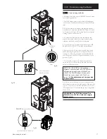
10.3
Fitting The Boiler
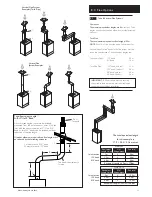
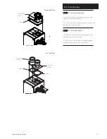
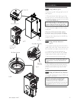
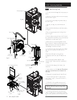
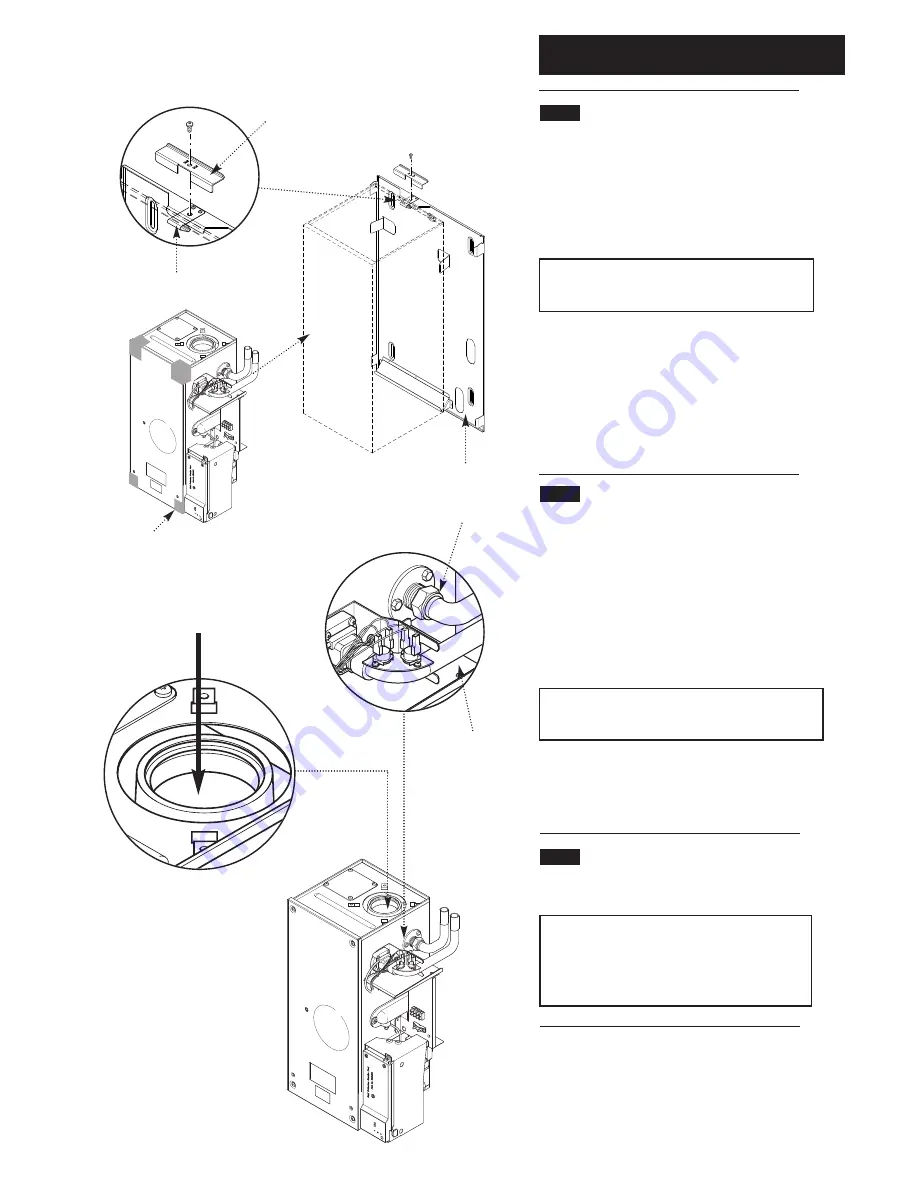
(Fig. 24)
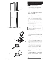
1. Remove the screw and retaining bracket from the wall
plate spring clip.
2. Offer up the boiler to the wall plate using the lifting
points shown in Fig. 24 and locate the rear bottom edge
onto the self locating support at the base of the wall plate.
(See
Safe Manual Handling
page 5.)
NOTE: When installing in a Loft/Small Compartment,
access for lifting the boiler from the front can be
gained for two people using the lifting points. (Fig. 24).
3. Rotate the boiler and engage into temporary spring
retaining latch.
4. Ensure the boiler is secured with the retaining
bracket and screw previously removed, immediately.
5. Remove thread protection caps from the FLOW and
RETURN connections.
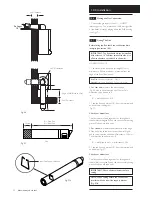
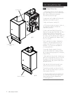
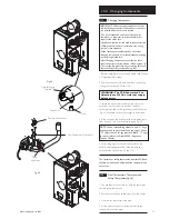
10.4
Making the Water Connections
(Fig. 25)
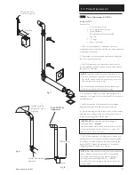
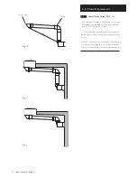
1. The boiler has two side water connections which are
labelled FLOW and RETURN. The front connection is the
flow pipe and the rear threaded connection is the return.
2. It is essential that the flow and return pipes are
connected to the boiler correctly. The flow connection
incorporates the boiler thermostats and a flow switch.
3. The boiler connection will accept 22mm fittings.
NOTE: On Promax 30 HE Plus models 28mm pipe
should be used to connect to the boiler flow and
return.
4. If the installation requires that the system pipework
originates from the bottom of the boiler, then the flow
and return pipes will need cutting, as they terminate
upwards.
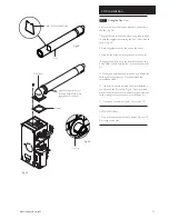
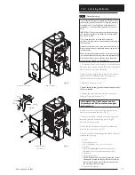
10.5
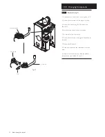
Making the Condensate Drain Connection
1. Connect the condensate drain using the 1”BSP nut and
seal supplied. (see section 7.6).
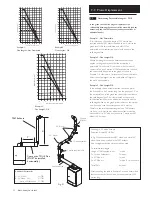
NOTE: To ensure the correct operation and
integrity of the condensate drainage system -
Carefully pour approximately 1 cupful (250ml) of
water into the flue products exhaust, at the top of the
heat exchanger (Fig. 25a) to ensure a seal is made in
the trap.
Return Pipe Connection
Flow Pipe
Connection
Suggested Lifting
Points shown as
shaded area
Wall Plate Spring Clip
Wall Plate
Retaining Bracket
Fig. 25
Fig. 24
Flue Products Exhaust
Fig. 25a


