


ODP 200H-II User’s Manual
13
ODP 200H-II User’s Manual
14
2-4. Dip Switch Setting
The printer is set up at the factory to be appropriate for almost all users. On the other hand,
offers some more settings for users with special requirements.
It has DIP switches that allow you to change communication setting, such as handshaking and
parity check, as well as print density.
Your printer has one set of DIP switches. The functions of the switches are shown in the following
tables.
♣Note : Power off. And open the cover of Dip Switch and change setting.
2-4-1. Serial Interface Specification
DIP Switch Set 1 Functions
SW
FUNCTION
ON
OFF
DEFAULT
2
Hexadecimal
HEXDUMP
NORMAL
OFF
5
Cut Mode
Full Cut
Partial Cut
OFF
6
Handshaking
XON/XOFF
DTR/DSR
OFF
8
Paper Low Mode
Paper Low
Do not detect
OFF
Baud rate selection
Transmission speed
SW-9
SW-10
115200 bps
ON
ON
9600 bps
OFF
ON
19200 bps
ON
OFF
38400 bps
OFF
OFF
Print Density
Print Density
SW-3
SW-4
Low Power
ON
ON
Normal
OFF
ON
Normal
ON
OFF
Dark
OFF
OFF
Signal tone selection
Signal tone selection
SW-1
SW-7
No signal tone
OFF
OFF
Short signal tone
OFF
ON
Medium signal tone
ON
OFF
Long signal tone
ON
ON
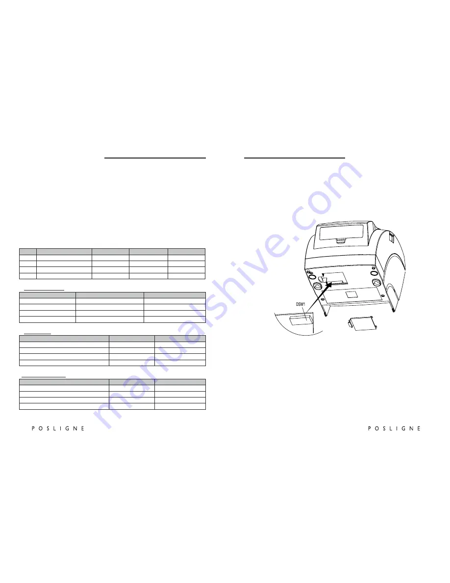
♣CAUTION:
Turn off the printer while removing the DIP switch cover to prevent an electric short, which can
damage the printer.
1. Make sure the printer is turned off.
2. Take out cutter cover
3. Remove the screw from the DIP switch cover
4. Set the switches using a pointed tool, such as tweezers or a small screwdriver.
5. Replace the DIP switch cover. Then, secure it with the screw.
The new settings take effect when you turn on the printer.